1. Introduction
deegree webservices are implementations of the geospatial webservice specifications of the Open Geospatial Consortium (OGC) and the INSPIRE Network Services. deegree webservices 3.4 includes the following services:
-
Web Feature Service (WFS): Provides access to raw geospatial data objects
-
Web Map Service (WMS): Serves maps rendered from geospatial data
-
Web Map Tile Service (WMTS): Serves pre-rendered map tiles
-
Catalogue Service for the Web (CSW): Performs searches for geospatial datasets and services
-
Web Processing Service (WPS): Executes geospatial processes
With a single deegree webservices installation, you can set up one of the above services, all of them or even multiple services of the same type. The remainder of this chapter introduces some notable features of the different service implementations and provides learning trails for learning the configuration of each service.
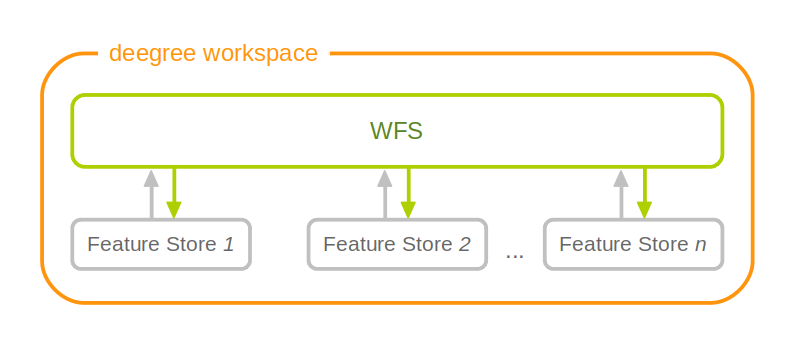
1.1. Characteristics of deegree WFS
deegree WFS is an implementation of the OGC Web Feature Service specification. Notable features:
-
Official OGC reference implementation for WFS 1.1.0 and WFS 2.0.0 Simple
-
Implements WFS standards 1.0.0, 1.1.0 and 2.0.0[1]
-
Fully transactional (even for rich data models)
-
Supports KVP, XML and SOAP requests
-
GML 2/3.0/3.1/3.2 output/input
-
Support for GetGmlObject requests and XLinks
-
High performance and excellent scalability
-
On-the-fly coordinate transformation
-
Designed for rich data models from the bottom up
-
Backends support flexible mapping of GML application schemas to relational models
-
ISO 19107-compliant geometry model: Complex geometries (e.g. non-linear curves)
-
Advanced filter expression support based on XPath 1.0
-
Supports numerous backends, such as PostGIS, Oracle Spatial, MS SQL Server, Shapefiles or GML instance documents
|
Tip
|
In order to learn the setup and configuration of a deegree-based WFS, we recommend to read chapters Installation and Getting started first. Check out Example workspace 1: INSPIRE Network Services and Example workspace 2: Utah Webmapping Services for example deegree WFS configurations. Continue with Configuration basics and Web Feature Service (WFS). |
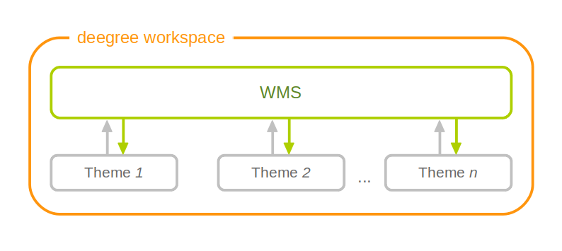
1.2. Characteristics of deegree WMS
deegree WMS is an implementation of the OGC Web Map Service specification. Notable features:
-
Official OGC reference implementation for WMS 1.1.1
-
Implements WMS standards 1.1.1 and 1.3.0[2]
-
Extensive support for styling languages SLD/SE versions 1.0.0 and 1.1.0
-
Supports KVP, XML and SOAP requests (WMS 1.3.0)
-
High performance and excellent scalability
-
High quality rendering
-
Scale dependent styling
-
Support for SE removes the need for a lot of proprietary extensions
-
Easy configuration of HTML and other output formats for GetFeatureInfo responses
-
Uses stream-based data access, minimal memory footprint
-
Nearly complete support for raster symbolizing as defined in SE (with some extensions)
-
Complete support for TIME/ELEVATION and other dimensions for both feature and raster data
-
Supports numerous backends, such as PostGIS, Oracle Spatial, Shapefiles or GML instance documents
-
Can render rich data models directly
|
Tip
|
In order to learn the setup and configuration of a deegree-based WMS, we recommend to read chapters Installation and Getting started first. Check out Example workspace 2: Utah Webmapping Services and Example workspace 1: INSPIRE Network Services for example deegree WMS configurations. Continue with Configuration basics and Web Map Service (WMS). |
1.3. Characteristics of deegree WMTS
deegree WMTS is an implementation of the OGC Web Map Tile Service specification. Notable features:
-
Implements Basic WMTS standard 1.0.0 (KVP)
-
High performance and excellent scalability
-
Supports different backends, such as GeoTIFF, remote WMS or file system tile image hierarchies
-
Supports on-the-fly caching (using EHCache)
-
Supports GetFeatureInfo for remote WMS backends
|
Tip
|
In order to learn the setup and configuration of a deegree-based WMTS, we recommend to read Installation and Getting started first. Continue with Configuration basics and Web Map Tile Service (WMTS). |
1.4. Characteristics of deegree CSW
deegree CSW is an implementation of the OGC Catalogue Service specification. Notable features:
-
Implements CSW standard 2.0.2
-
Fully transactional
-
Supports KVP, XML and SOAP requests
-
High performance and excellent scalability
-
ISO Metadata Application Profile 1.0.0
-
Pluggable and modular dataaccess layer allows to add support for new APs and backends
-
Modular inspector architecture allows to validate records to be inserted against various criteria
-
Standard inspectors: schema validity, identifier integrity, INSPIRE requirements
-
Handles all defined queryable properties (for Dublin Core as well as ISO profile)
-
Complex filter expressions
|
Tip
|
In order to learn the setup and configuration of a deegree-based CSW, we recommend to read Installation and Getting started first. Check out Example workspace 3: An ISO Catalogue Service setup for an example deegree CSW configuration. Continue with Configuration basics and Catalogue Service for the Web (CSW). |
1.5. Characteristics of deegree WPS
deegree WPS is an implementation of the OGC Processing Service specification. Notable features:
-
Implements WPS standard 1.0.0
-
Supports KVP, XML and SOAP requests
-
Pluggable process provider layer
-
Easy-to-use API for implementing Java processes
-
Supports all variants of input/output parameters: literal, bbox, complex (binary and xml)
-
Streaming access for complex input/output parameters
-
Processing of huge amounts of data with minimal memory footprint
-
Supports storing of response documents/output parameters
-
Supports input parameters given inline and by reference
-
Supports RawDataOutput/ResponseDocument responses
-
Supports asynchronous execution (with polling of process status)
|
Tip
|
In order to learn the setup and configuration of a deegree-based WPS, we recommend to readInstallation and Getting started first. Check out Example workspace 4: Web Processing Service demo for an example deegree WPS configuration. Continue with Configuration basics and Web Processing Service (WPS). |
2. Installation
2.1. System requirements
deegree webservices work on any platform with a compatible Java SE 8 installation, including:
-
Microsoft Windows
-
Linux
-
MacOS
Supported Java SE 8 versions are Oracle JDK 8 [3] and OpenJDK 8 [4].
|
Note
|
Newer Java SE versions such as the LTS versions 11 and 16 are currently not supported by deegree 3.4. Please check out our wiki page Java 11 support for further information. |
2.2. Downloading
deegree webservices downloads are available on the deegree home page. You have the choice between:
|
Tip
|
If you are confused by the options and unsure which version to pick, use the ZIP. All variants contain exactly the same deegree webservices webapp, they only differ in packaging. |
2.3. Starting and stopping
In order to run the ZIP version, extract it into a local directory of your
choice. Afterwards, change to the directory deegree-webservices-tomcat-bundle-3.4.x/apache-tomcat-8.x.y/bin and
fire up the included start script for your operating system:
-
Windows: startup.bat
-
Linux/MacOS: startup.sh (when starting via a Desktop Environment, choose "Run in terminal", and you may need to grant permission to execute the scripts with
chmod a+x *.shbefore)
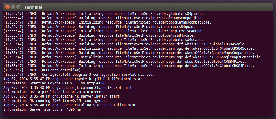
You should now see a terminal window on your screen with a lot of log messages:
|
Tip
|
If you don’t see this terminal window, make sure that the java command is on the system path. You can verify this by entering java -version at the command prompt. Also ensure that JAVA_HOME system environment variable points to the correct installation directory of a compatible JDK. |
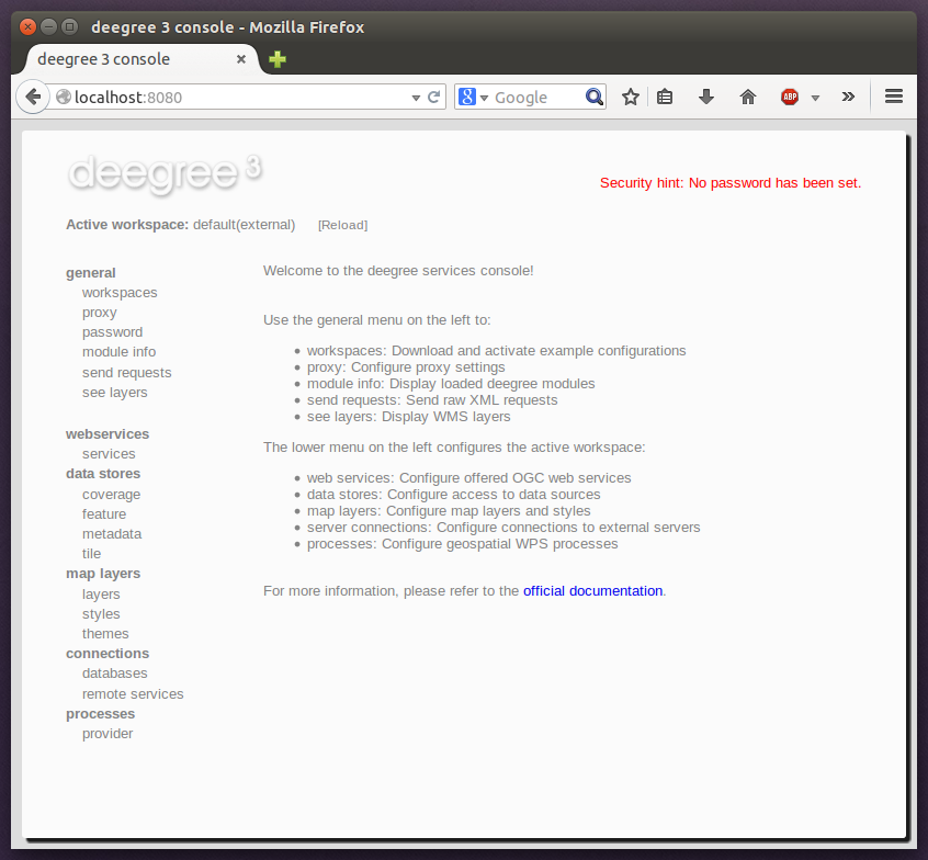
You may minimize this window, but don’t close it as long as you want to be able to use the deegree webservices. In order to check if the services are actually running, open http://localhost:8080 in your browser. You should see the following page:
To shut deegree webservices down, switch back to the terminal window and press CTRL+C or simply close it.
|
Tip
|
If you want to run deegree webservices on system startup automatically, consider installing Apache Tomcat 8 as a system service. Afterwards, download the WAR version of deegree webservices and deploy it into your Tomcat installation (e.g. by copying the WAR file into the webapps folder). Consult the Tomcat documentation for more information and options. |
2.4. Securing deegree
Most weaknesses in deegree come from incorrect or inappropriate configuration. It is nearly always possible to make deegree more secure than the default out of the box configuration. The following documents best practices and recommendations on securing a production deegree server, whether it be hosted on a Windows or Unix based operating system.
2.4.1. Software Versions
The first step is to make sure you are running the latest stable releases of software:
-
Operating System including the latest updates and security patches
-
Java Runtime Environment (JRE) or JDK
-
Apache Tomcat, Jetty or your preferred Java Servlet container
-
Third-party libraries such as GDAL, JDBC driver, and
-
deegree webservices itself.
|
Tip
|
If you are running Apache Tomcat we recommend that you read and apply all recommendations as documented in Apache Tomcat Security Considerations. |
2.4.2. Encryption
When operating deegree in a production environment enable HTTPS with SSL or TLS. Either enable HTTPS on your Java Servlet Container or operate it behind a web server such as Apache httpd oder NGINX.
|
Tip
|
If you are running Apache Tomcat read the SSL HowTo. |
2.4.3. Securing deegree console and REST API
It is as a huge security problem to operate the deegree web app without setting a password for the deegree console. How to set the password for the deegree console is described in Configuration basics. The same applies to the deegree REST API. Since both transfer the credentials as clear text (with a little bit of obscurity) it is highly recommended to enable encryption on the protocol level as described above! For further information how to protect the deegree REST API read more in deegree REST interface. You should also consider to limit the access to both resources. Apply a filter by IP or hostname to only allow a subset of machines to connect and access the deegree console and REST API.
|
Warning
|
The deegree console provides access to the server file system. Therefore you must not operate the Java Servlet container as root user! Furthermore you should consider to enable the Java Security Manager and define restrictive file permissions.[8] |
3. Getting started
In the previous chapter, you learned how to install and start deegree webservices. In this chapter, we will introduce the deegree service console and learn how to use it to perform basic tasks such as downloading and activating example configurations. In deegree terminology, a complete configuration for a deegree instance is called "deegree workspace".
The following chapters describe the structure and the aspects of the deegree workspace in detail. For the remainder of this chapter, just think of a deegree workspace as a directory of configuration files that contains a complete configuration for a deegree webservice instance. You may have multiple deegree workspaces on your machine, but only a single workspace can be active.
3.1. Accessing deegree’s service console
The service console is a web-based administration interface for configuring your deegree webservices installation. If deegree webservices are running on your machine, you can usually access the console from your browser via http://localhost:8080
|
Tip
|
If you’re not running the ZIP version, but deployed the WAR version into a web container, you most probably will have to use a different URL for accessing the console, e.g. http://localhost:8080/deegree-webservices-3.4.18. The port number and webapp name depend on your installation/deployment details. |
|
Tip
|
You can access the service console from other machines on your network by exchanging localhost with the name or IP address of the machine that runs deegree webservices. |
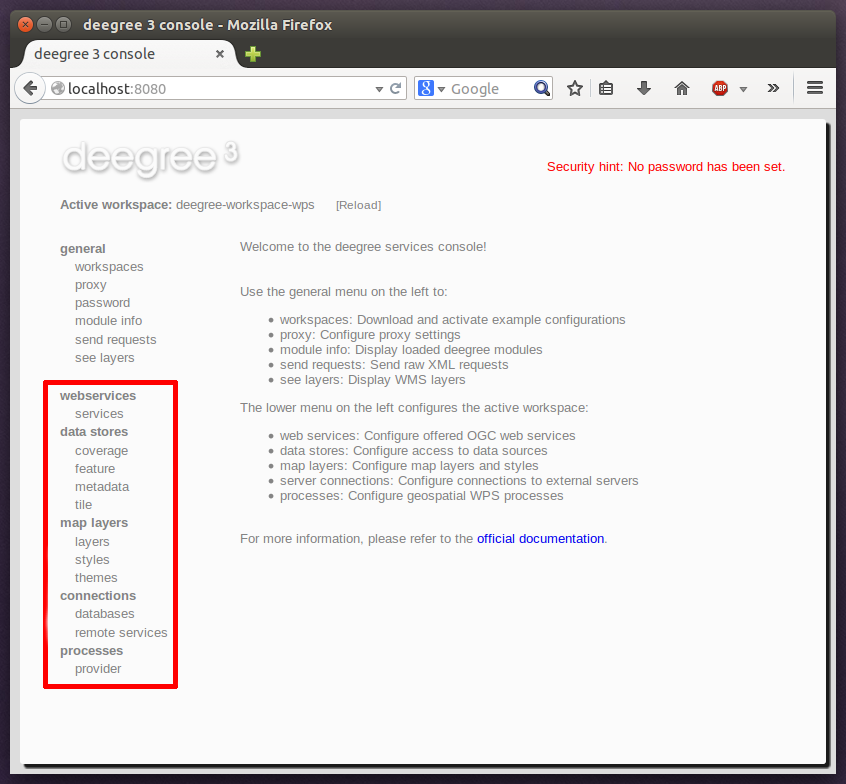
For the remainder of the chapter, only the general section is relevant. The menu items in this section:
-
workspaces: Download and activate example configurations
-
proxy: Configure network proxy settings
-
password: Set a password for accessing the service console
-
module info: Display loaded deegree modules
-
send requests: Send raw OGC web service requests
-
see layers: Display WMS layers
3.1.1. Downloading and activating example workspaces
Click the workspaces link on the left:
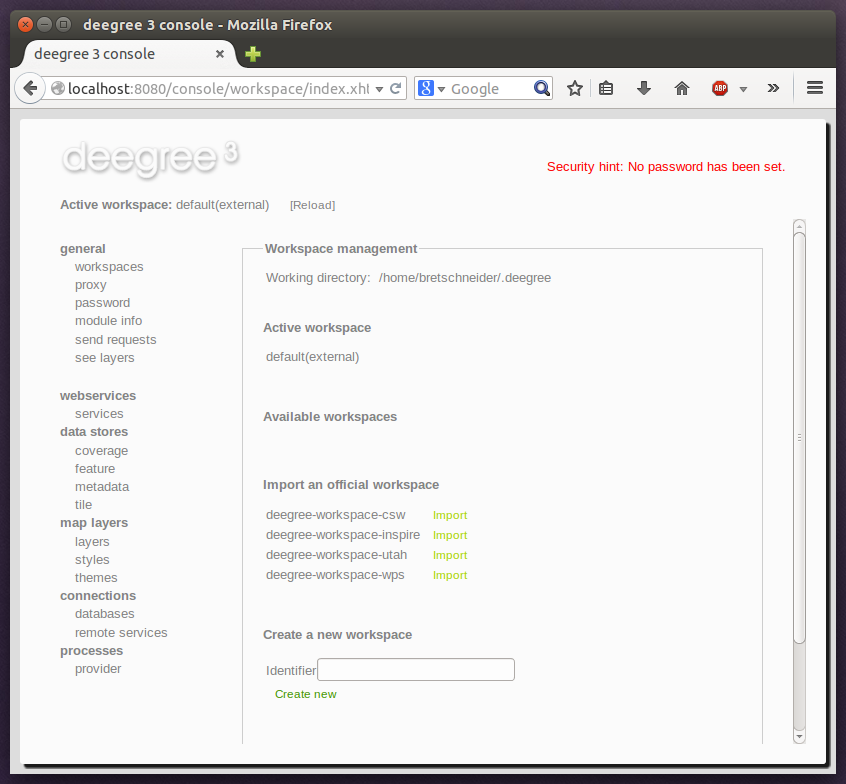
The bottom of the workspaces view lists example workspaces provided by the deegree project. You should see the following items:
-
deegree-workspace-csw: Example workspace 3: An ISO Catalogue Service setup
-
deegree-workspace-inspire: Example workspace 1: INSPIRE Network Services
-
deegree-workspace-utah: Example workspace 2: Utah Webmapping Services
-
deegree-workspace-wps: Example workspace 4: Web Processing Service demo
|
Tip
|
If the machine running deegree webservices uses a proxy to access the internet and you don’t see any available example configurations, you will probably have to configure the proxy settings. Ask your network administrator for details and use the proxy link to setup deegree’s proxy settings. |
If you click Import, the corresponding example workspace will be fetched from the artifact repository of the deegree project and extracted in your deegree workspaces folder. Depending on the workspace and your internet connection, this may take a while (the Utah workspace is the largest one and about 70 MB in size).
After downloading has completed, the new workspace will be listed in section "Available workspaces":
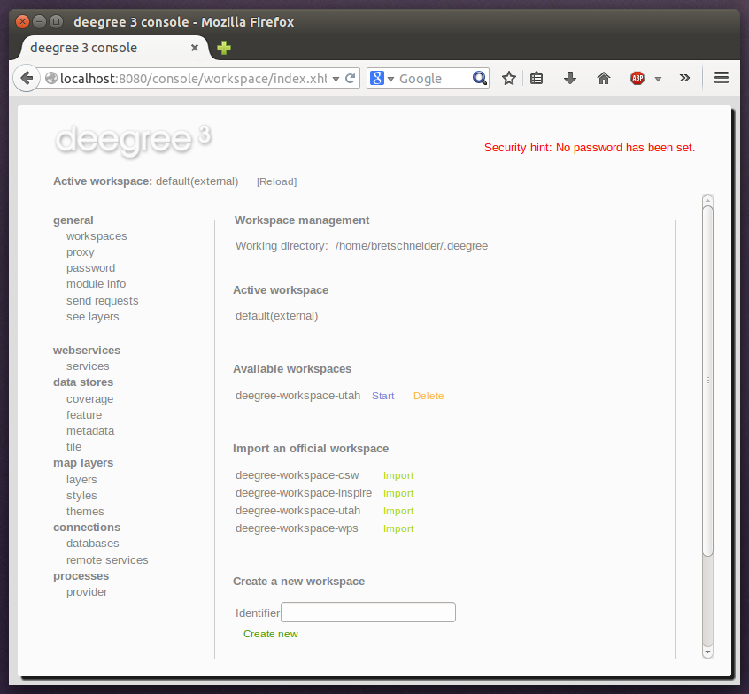
You can now activate the downloaded workspace by clicking Start. Again, this may take a bit, as it may require some initialization. The workspace will be removed from the list of inactive workspaces and displayed next to "Active workspace:" (below the deegree logo). Your deegree instance is now running the configuration that is contained in the downloaded workspace.
3.2. Example workspace 1: INSPIRE Network Services
This workspace is a basic INSPIRE View and Download Services setup. It contains a transactional WFS (2.0.0 and 1.1.0) configured for all Annex I Data Themes and a WMS (1.3.0 and 1.1.1) that is configured for three layers from three Annex I Data Themes. The workspace contains some harmonized dutch base data for Administrative Units, Cadastral Parcels and Addresses. The WFS is configured to behave as an INSPIRE Download service (Direct Access) that delivers the base data as valid, harmonized INSPIRE GML and supports rich querying facilities.
|
Tip
|
This workspace is pre-configured to load harmonized INSPIRE features from GML files into memory, but can easily be adapted to use PostGIS, Oracle Spatial or Microsoft SQL Server databases as storage backend (see Auto-generating a mapping configuration and tables and SQL feature store). |
After downloading and activating the "deegree-workspace-inspire" workspace, you can click the see layers link, which opens a simple map client that displays a base map (not rendered by deegree, but loaded from the OpenStreetMap servers).
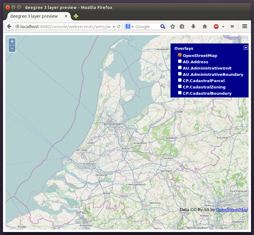
Click the + on the right to see a list of available layers. You can now tick the INSPIRE layers offered by the deegree WMS.
|
Tip
|
The map client is based on OpenLayers. Drag the map by holding the mouse button and moving your mouse. Zoom using the controls on the left or with the mouse wheel. Alternatively, you can open a zoom rectangle by holding the SHIFT key and clicking the mouse button in the map area. |
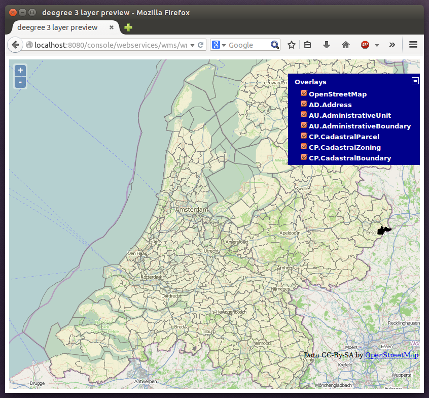
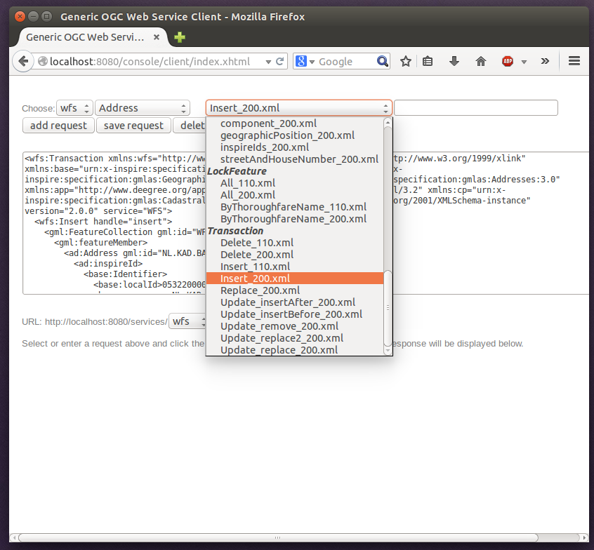
Note that nothing will be rendered for layer AD.Address, as the configured storage (memory) doesn’t contain any Address features yet. However, the workspace ships with example WFS-T requests that can be used to insert a few harmonized INSPIRE Address features. Use the send requests link in the service console to access the example requests (you may need to go back in your browser first):
Use the third drop-down menu to select an example request. Entries Insert_200.xml or Insert_110.xml can be used to insert a small number of INSPIRE Address features using WFS-T insert requests:
Click Send to execute the request. After successful insertion, the internal storage contains a few addresses, and you may want to move back to the layer overview (see layers). If you activate layer AD.Address this time, the newly inserted features will be rendered by the deegree WMS (look for them in the area of Enkhuizen):

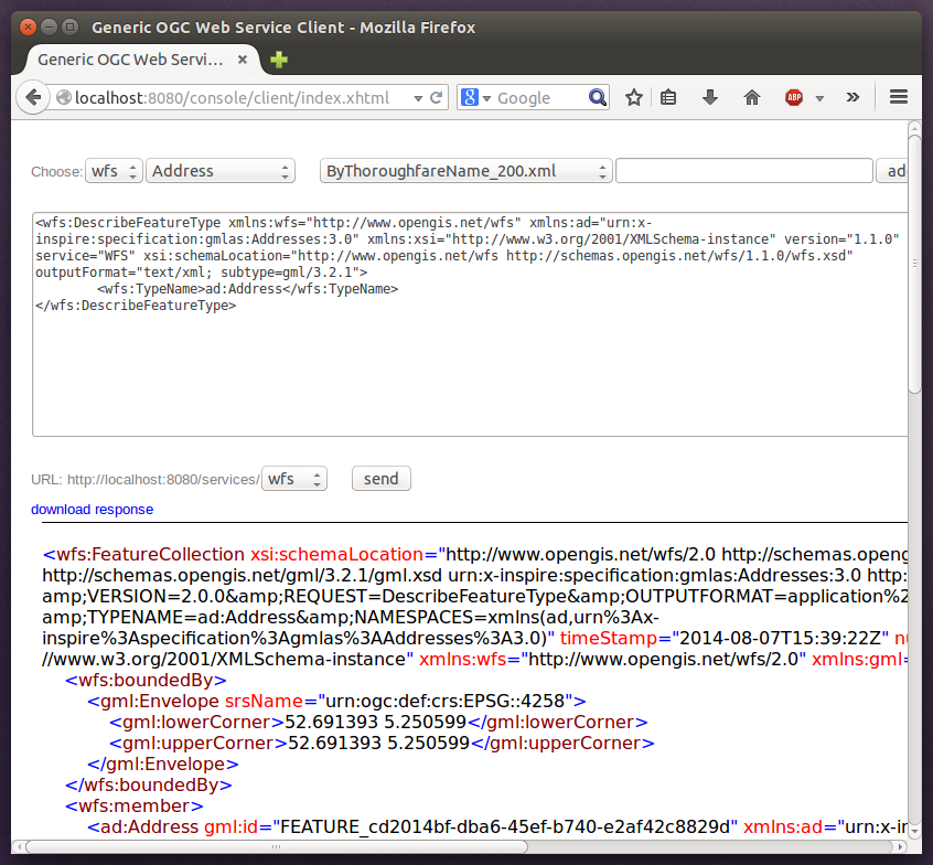
The example requests also contain a lot of query examples, e.g. requesting of INSPIRE Addresses by street name:
|
Tip
|
This workspace is a good starting point for implementing scalable and compliant INSPIRE View and/or Download Services. It can easily be adapted to use PostGIS, Oracle Spatial or Microsoft SQL Server databases as storage backend (see Auto-generating a mapping configuration and tables and SQL feature store). Other things you may want to adapt is the configuration of Map layers, the Map styles or the reported Metadata. |
|
Tip
|
You can also delete features using WFS transactions. After deletion, they will not be rendered anymore as WMS and WFS operate on the same feature store. |
3.3. Example workspace 2: Utah Webmapping Services
The Utah example workspace contains a web mapping setup based on data from the state of Utah. It contains a WMS configuration (1.3.0 and 1.1.1) with some raster and vector layers and some nice render styles. Raster data is read from GeoTIFF files, vector data is backed by shapefiles. Additionally, a WFS (2.0.0, 1.1.0 and 1.0.0) is configured that allows to access the raw vector data in GML format.
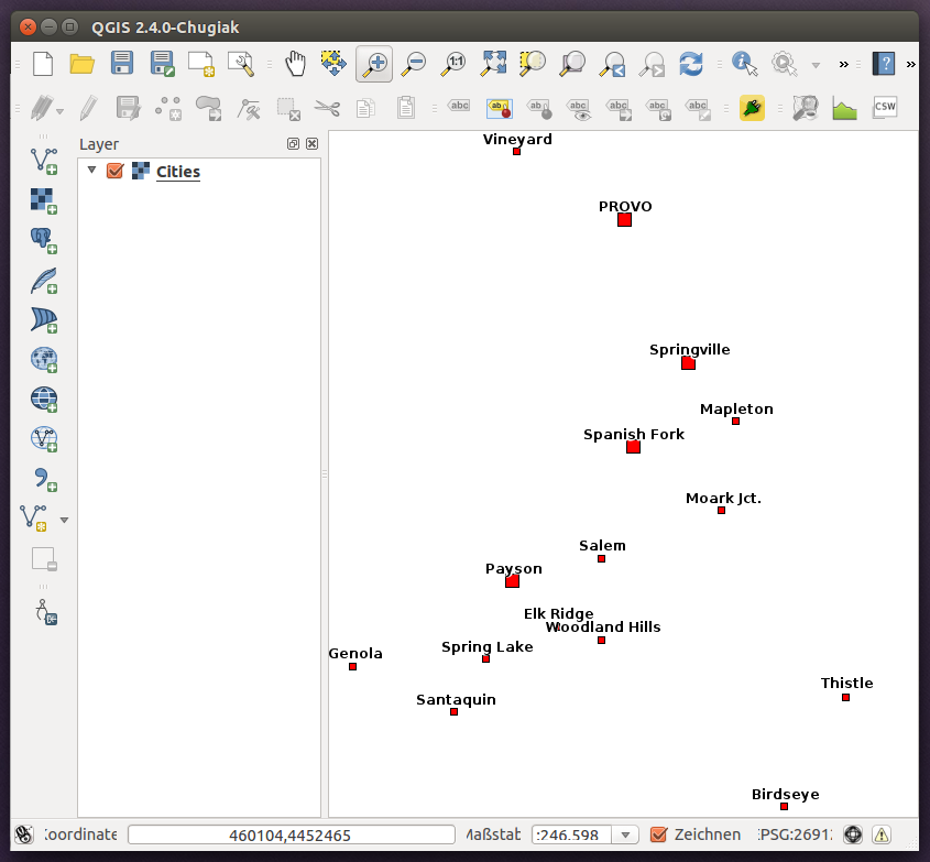
After downloading and activating the "deegree-workspace-utah" workspace, you can click on the see layers link, which opens a simple map client that displays a base map (not rendered by deegree, but loaded from the OpenStreetMap servers).
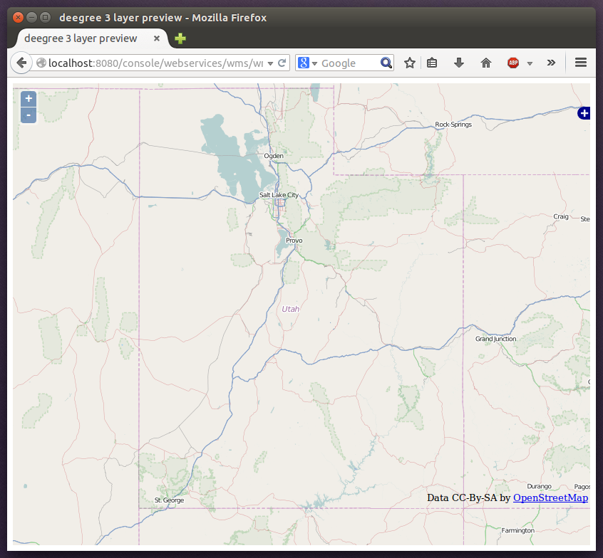
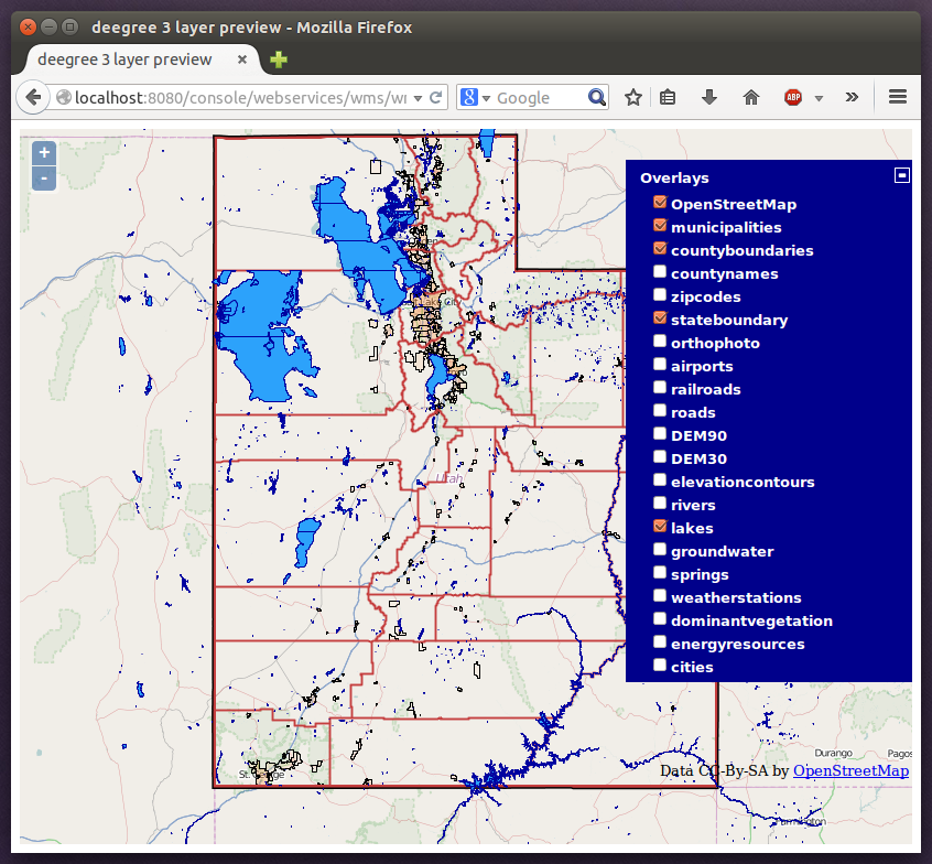
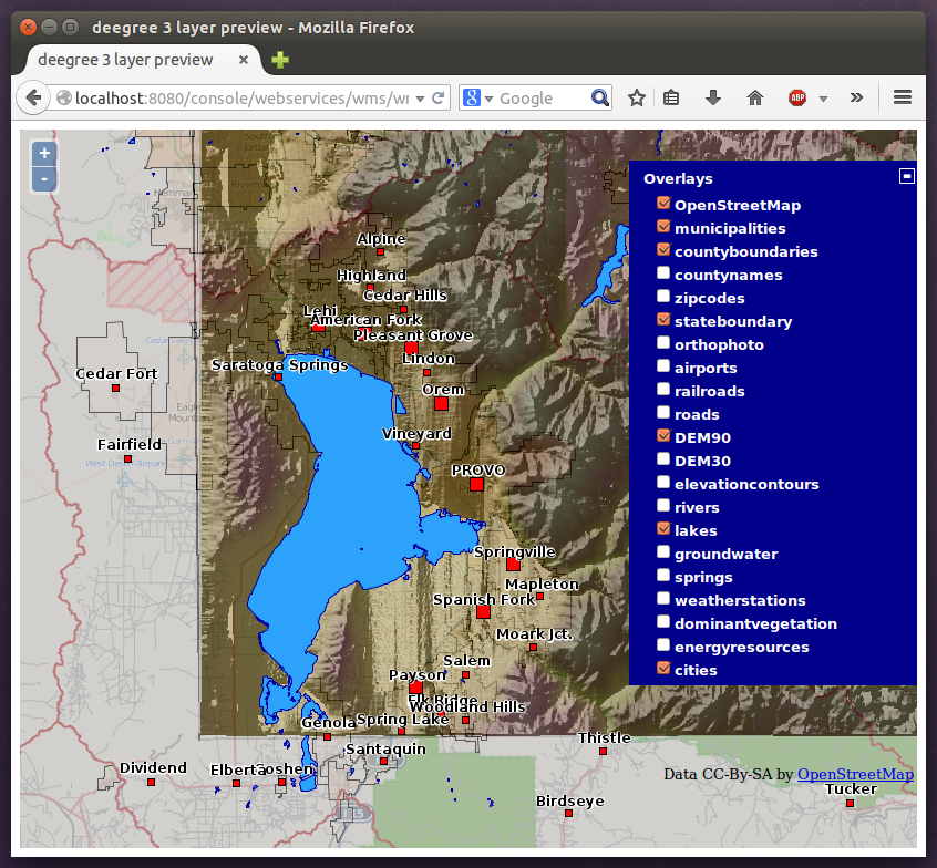
Click the + on the right to see a list of available layers. Tick the ones you want to see. They will be rendered by your deegree webservices instance.
|
Tip
|
The map client is based on OpenLayers. Drag the map by holding the mouse button and moving your mouse. Zoom using the controls on the left or with the mouse wheel. Alternatively, you can open a zoom rectangle by holding the SHIFT key and clicking the mouse button in the map area. |
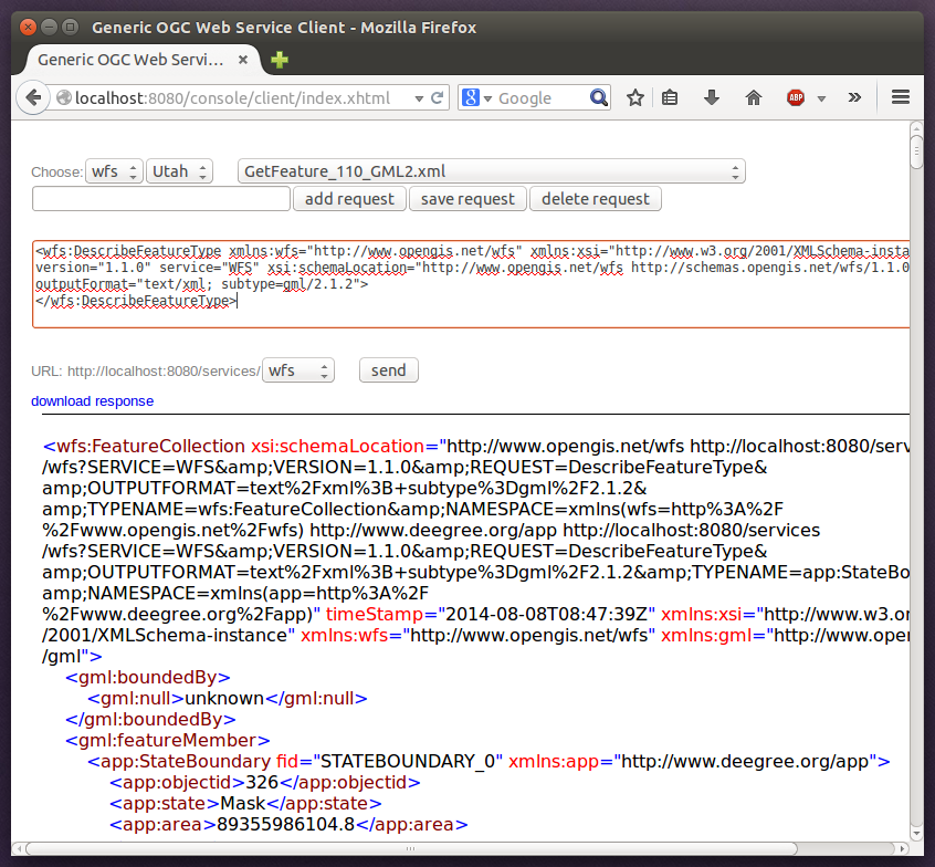
In order to send requests against the WFS, you may use the send requests link in the service console (you may need to go back in your browser first). A simple interface for sending XML requests will open up. This interface is meant for accessing OGC web services on the protocol level and contains some reasonable example requests.
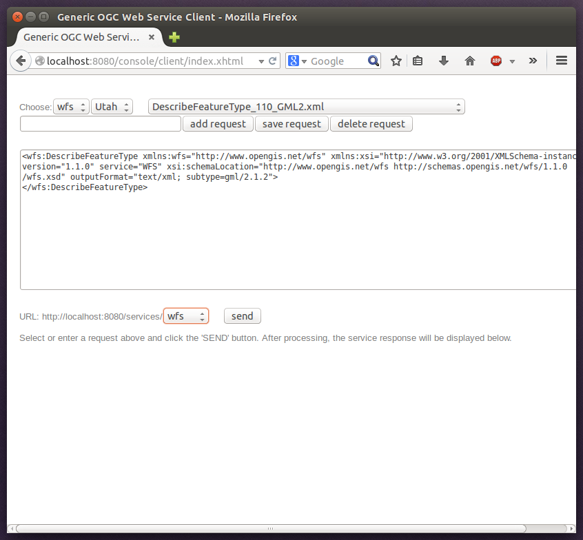
Select one of the example requests from the third drop-down menu and click Send. The server response will be displayed in the lower section.
|
Tip
|
WFS request types and their format are specified in the OGC Web Feature Service specification. |
|
Tip
|
Instead of using the built-in layer preview or the generic OGC client, you may use any compliant OGC client for accessing the WMS and WFS. Successfully tested desktop clients include Quantum GIS (install WFS plugin for accessing WFS), uDig, OpenJUMP and deegree iGeoDesktop. The service address to enter in your client is: http://localhost:8080/services. |
3.4. Example workspace 3: An ISO Catalogue Service setup
This workspace contains a catalogue service (CSW) setup that complies to the ISO Application Profile. After downloading and starting it, you will have to setup tables in a PostGIS database first. You will need to have an empty and spatially-enabled PostGIS database handy that can be accessed from the machine that runs deegree webservices.
|
Tip
|
Instead of PostGIS, you can also use the workspace with an Oracle Spatial or a Microsoft SQL Server database. In order to enable support for these databases, see Adding database modules. |
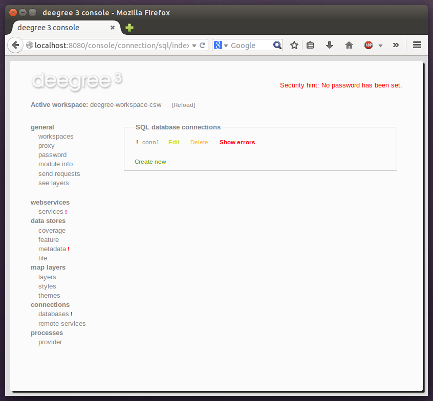
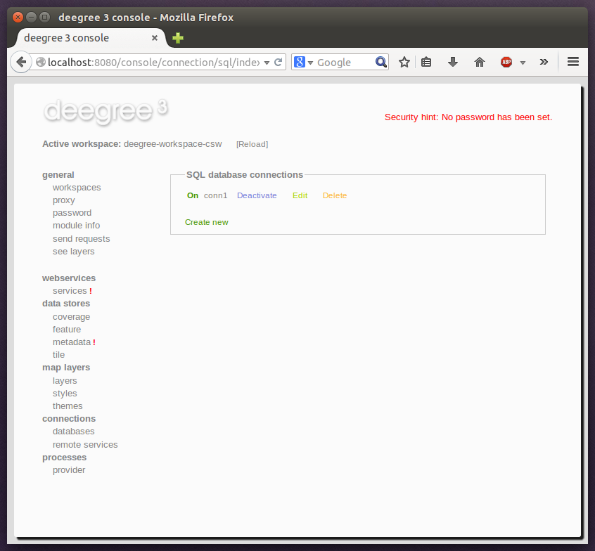
After downloading and starting the workspace, some errors will be indicated (red exclamation marks):

Don’t worry, this is just because we’re missing the correct connection information to connect to our database. We’re going to fix that right away. Click connections → databases:
Click Edit:
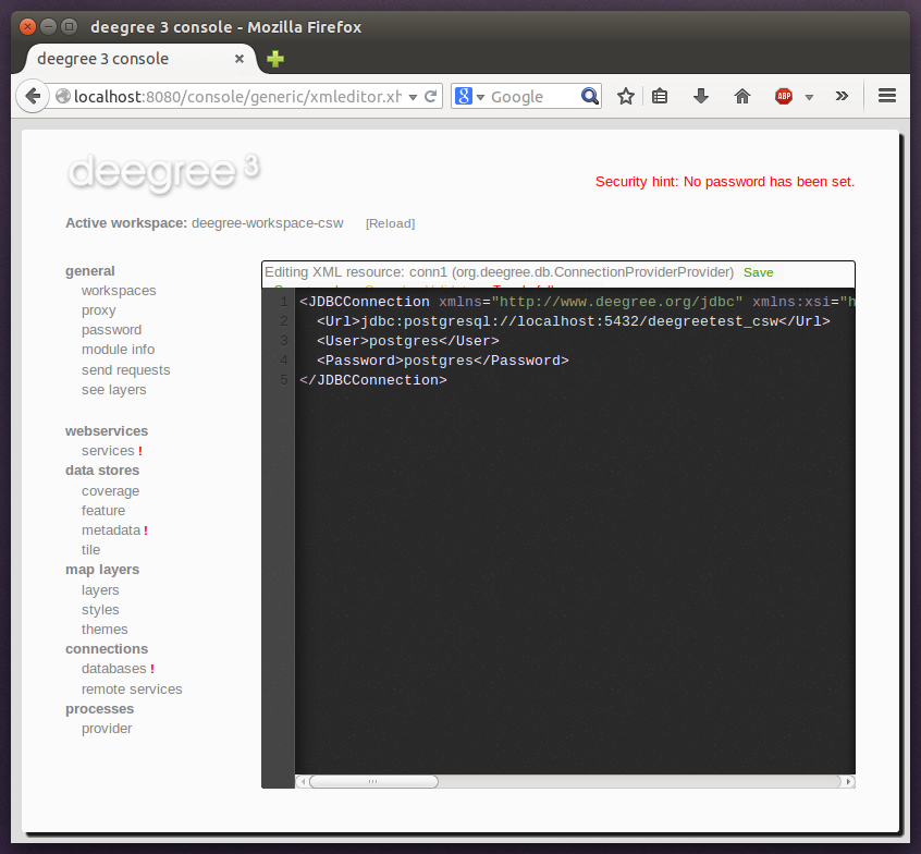
Make sure to enter the correct connection parameters and click Save. You should now have a working connection to your database, and the exclamation mark for conn1 should disappear. Click Reload to force a full reinitialization of the workspace:
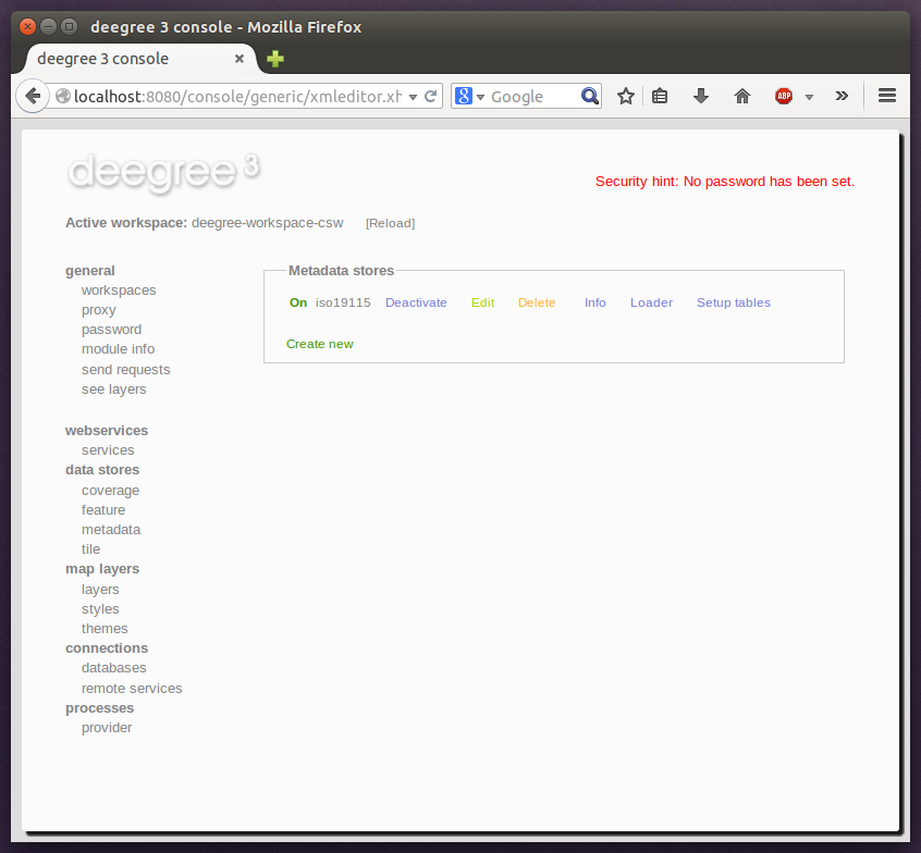
The indicated problems are gone now, but we still need to create the required database tables. Change to the metadata store view (data stores → metadata) and click Setup tables:
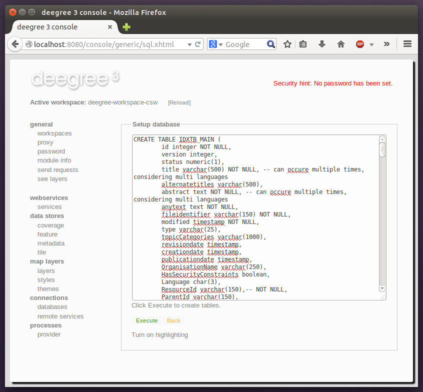
In the next view, click Execute:
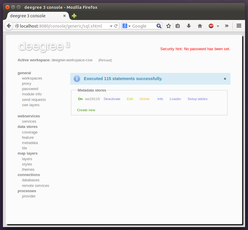
If all went well, you should now have a working, but empty CSW setup. You can connect to the CSW with compliant clients or use the send requests link to send raw CSW requests to the service. The workspace comes with some suitable example requests. Use the third drop-down menu to select an example request. Entry complex_insert.xml can be used to insert some ISO example records using a CSW transaction request:
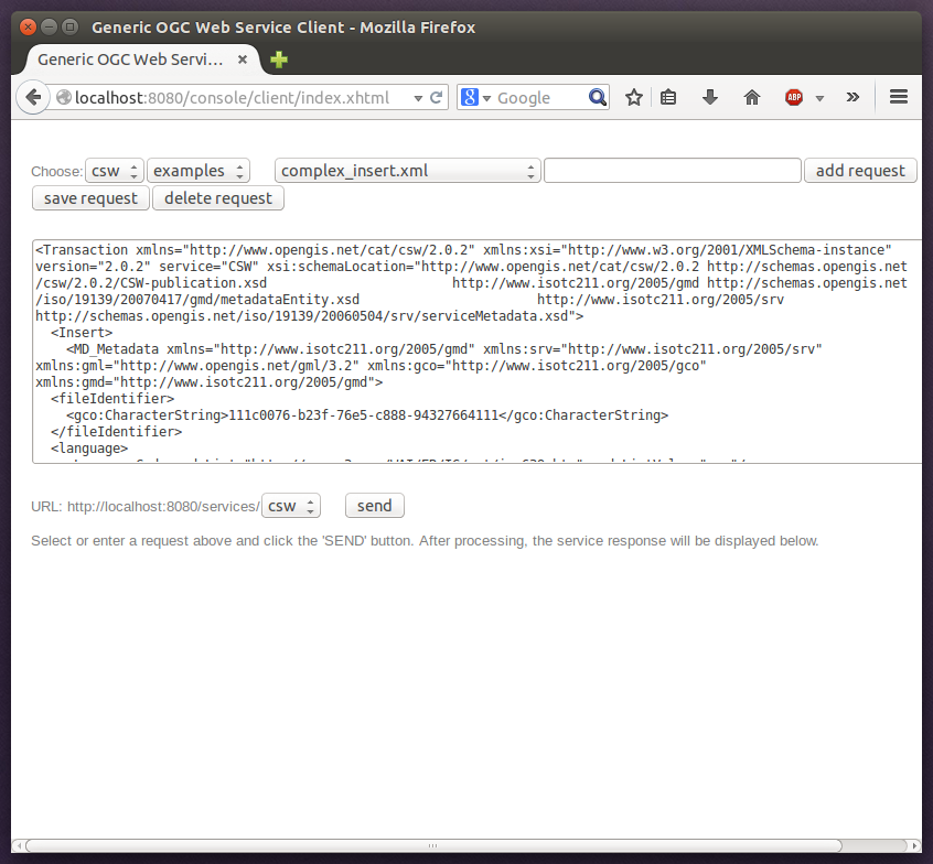
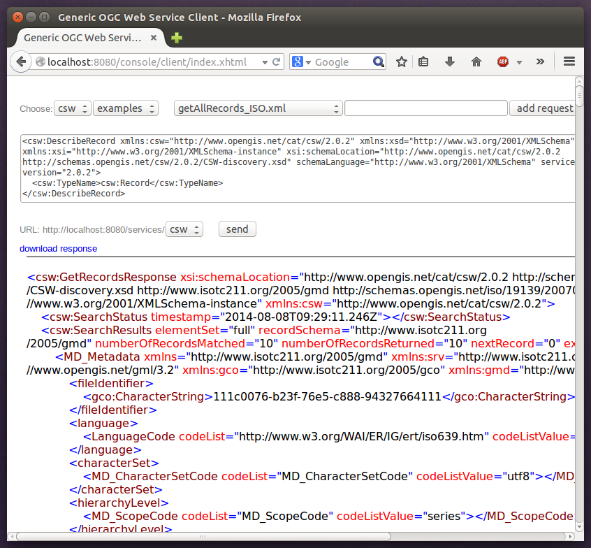
Click Send. After successful insertion, some records have been inserted into the CSW (respectively the database). You may want to explore other example requests as well, e.g. for retrieving records:
3.5. Example workspace 4: Web Processing Service demo
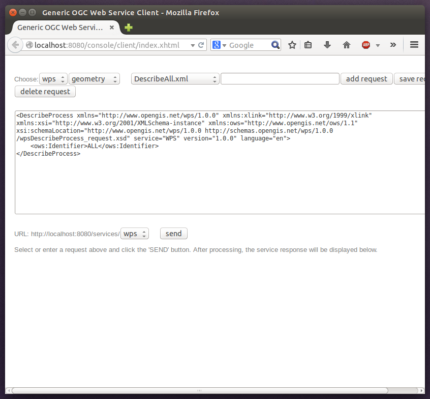
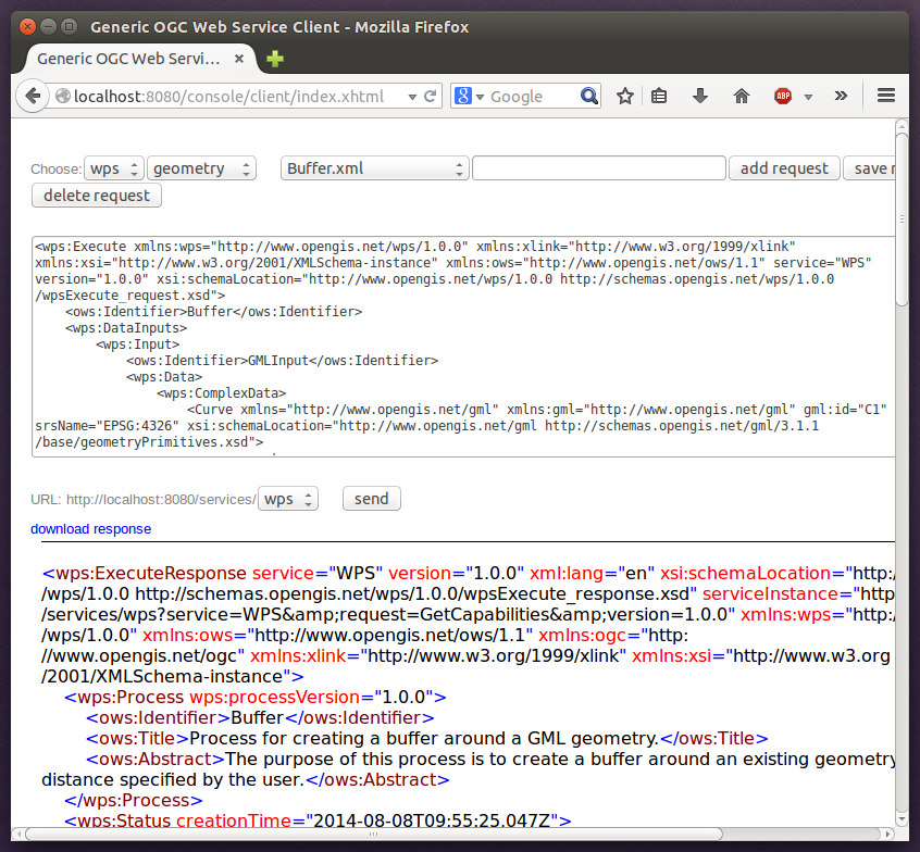
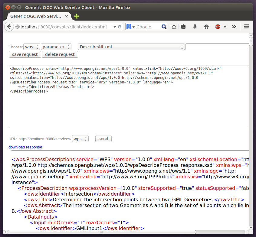
This workspace contains a WPS setup with simple example processes and example requests. It’s a good starting point for learning the WPS protocol and the development of WPS processes. After downloading and starting it, click send requests in order to find example requests that can be sent to the WPS. Use the third drop-down menu to select an example request:
Click Send to fire it against the WPS:
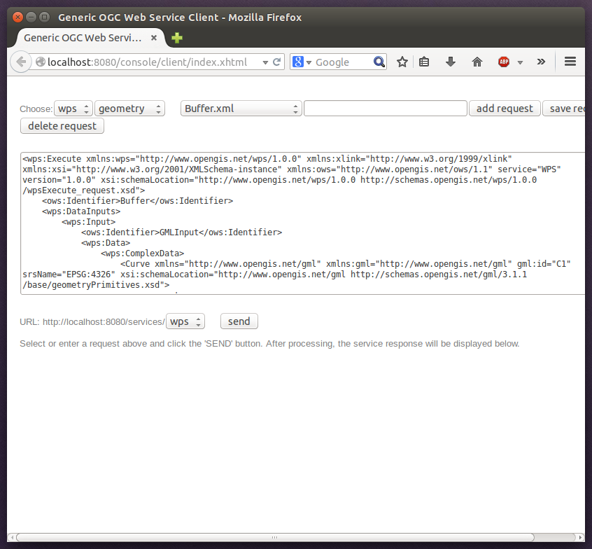
The response of the WPS will be displayed in the lower section:
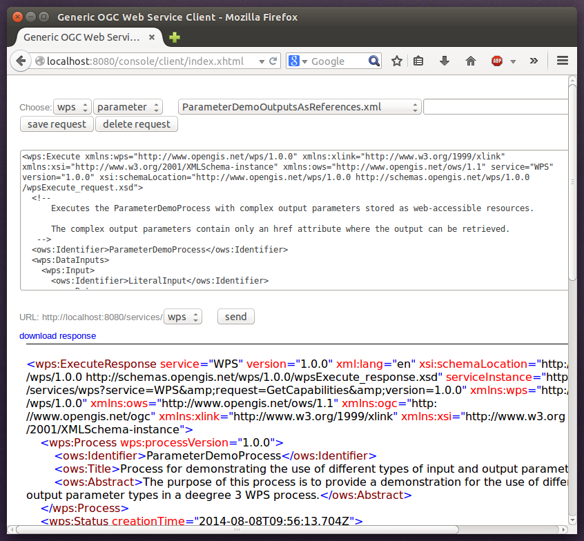
Besides the geometry example processes, the parameter example process and example requests may be interesting to developers who want to learn development of WPS processes with deegree webservices:
The process has four input parameters (literal, bounding box, xml and binary) that are simply piped to four corresponding output parameters. There’s practically no process logic, but the included example requests demonstrate many of the possibilities of the WPS protocol:
-
Input parameter passing variants (inline vs. by reference)
-
Output parameter handling (inline vs. by reference)
-
Response variants (ResponseDocument vs. RawData)
-
Storing of response documents
-
Asynchronous execution
|
Tip
|
WPS request types and their format are specified in the OGC Web Processing Service specification. |
|
Tip
|
In order to add your own processes, see Web Processing Service (WPS) and Process providers. |
4. Configuration basics
In the previous chapter, you learned how to access and log in to the deegree service console and how to download and activate example workspaces. This chapter introduces the basic concepts of deegree webservices configuration:
-
The deegree workspace and the active workspace directory
-
Workspace files and resources
-
Workspace directories and resource types
-
Resource identifiers and dependencies
-
Usage of the service console for workspace configuration
The final section of this chapter describes recommended practices for creating your own workspace. The remaining chapters of the documentation describe the individual workspace resource formats in detail.
4.1. The deegree workspace
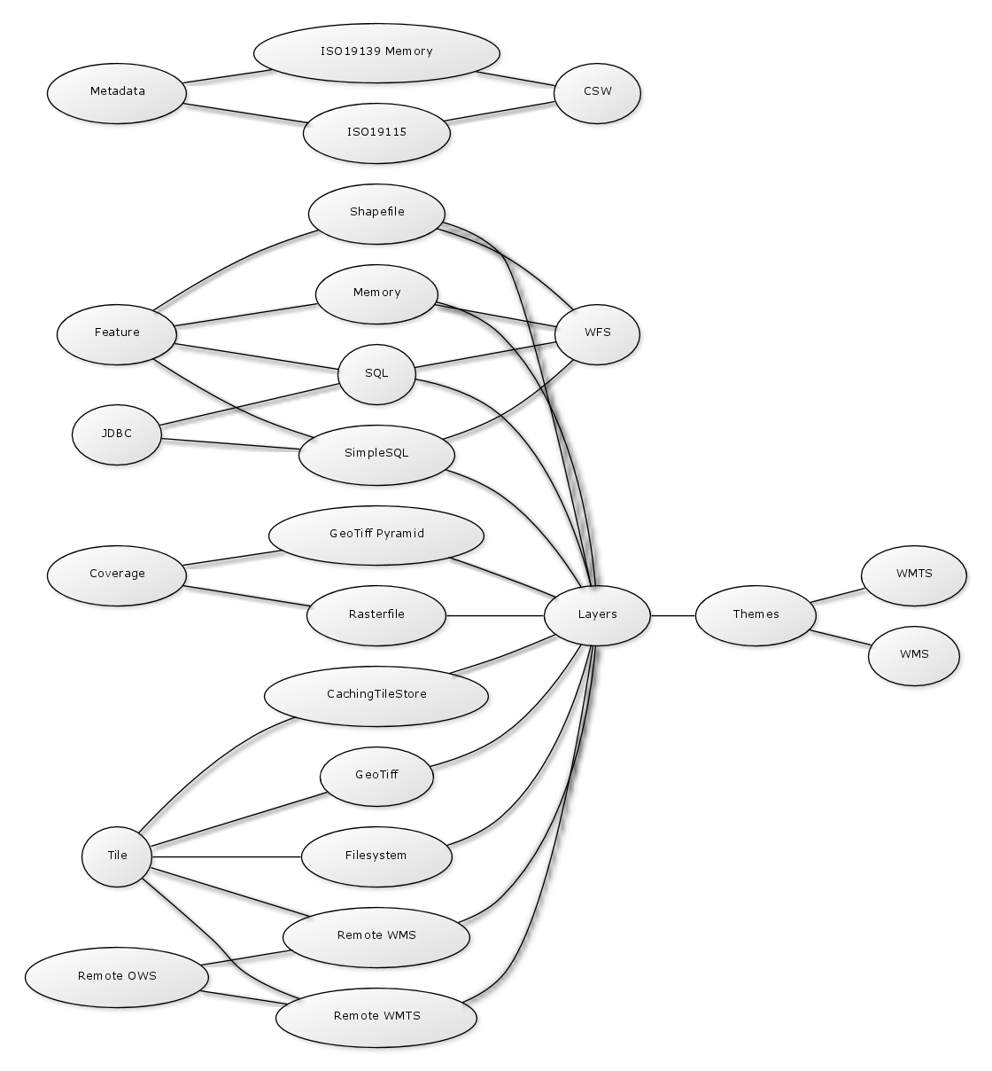
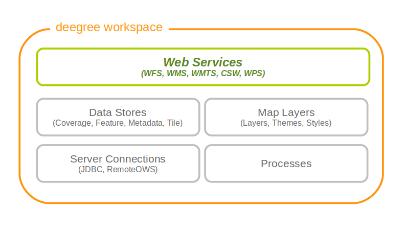
The deegree workspace is the modular, resource-oriented and extensible configuration concept used by deegree webservices. The following diagram shows the different types of resources that it contains:
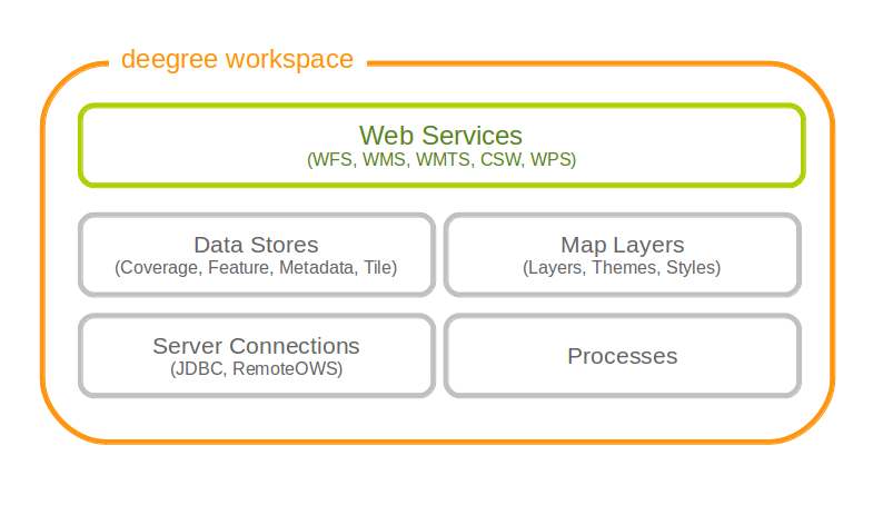
The following table provides a short description of the different types of workspace resources:
| Resource type | Description |
|---|---|
Web Services |
Web services (WFS, WMS, WMTS, CSW, WPS) |
Data Stores (Coverage) |
Coverage (raster) data access (GeoTIFFs, raster pyramids, etc.) |
Data Stores (Feature) |
Feature (vector) data access (Shapefiles, PostGIS, Oracle Spatial, etc.) |
Data Stores (Metadata) |
Metadata record access (ISO records stored in PostGIS, Oracle, etc.) |
Data Stores (Tile) |
Pre-rendered map tiles (GeoTIFF, image hierarchies in the file system, etc.) |
Map Layers (Layer) |
Map layers based on data stores and styles |
Map Layers (Style) |
Styling rules for features and coverages |
Map Layers (Theme) |
Layer trees based on individual layers |
Processes |
Geospatial processes for the WPS |
Server connections (JDBC) |
Connections to SQL databases |
Server connections (remote OWS) |
Connections to remote OGC web services |
Physically, every configured resource corresponds to an XML configuration file in the active workspace directory.
4.2. Dependencies of the deegree configuration files
The following diagram shows the different types of resources and their dependencies. The deegree configuration can be divided into several sections:
-
web services
-
data stores
-
map layers
-
server connections
For example, to offer a Web Feature Service, a feature store (based on a shapefile, database, etc) must be configured. With a rasterfile, like a GeoTIFF, you can configured a tile store and a coverage store to offer a Web Map Service.
4.3. Location of the deegree workspace directory
The active deegree workspace is part of the .deegree directory which stores a few global configuration files along with the workspace. The location of this directory depends on your operating system.
4.3.1. Linux/Solaris/Mac OS X
On UNIX-like systems (Linux/Solaris/MacOS X), deegree’s configuration files are located in folder <$HOME/.deegree/. Note that $HOME is determined by the user that started the web application container that runs deegree. If you started the ZIP version of deegree as user "kelvin", then the directory will be something like /home/kelvin/.deegree.
|
Tip
|
In order to use a different folder for deegree’s configuration files, you can set the system environment variable DEEGREE_WORKSPACE_ROOT. Note that the user running the web application container must have read/write access to this directory. |
4.3.2. Windows
On Windows, deegree’s configuration files are located in folder %USERPROFILE%/.deegree/. Note that %USERPROFILE% is determined by the user that started the web application container that runs deegree. If you started the ZIP version of deegree as user "kelvin", then the directory will be something like C:\Users\kelvin\.deegree or C:\Dokumente und Einstellungen\kelvin\.deegree.
|
Tip
|
In order to use a different folder for deegree’s configuration files, you can set the system environment variable DEEGREE_WORKSPACE_ROOT. Note that the user running the web application container must have read/write access to this directory. |
4.3.3. Global configuration files and the active workspace
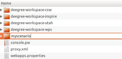
If you downloaded all four example workspaces (as described in Getting started), set a console password and the proxy parameters, your .deegree directory will look like this:
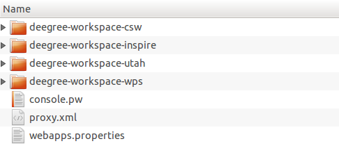
As you see, this .deegree directory contains four subdirectories. Every subdirectory corresponds to a deegree workspace. Besides the configuration files inside the workspace, three global configuration files exist:
| File name | Function |
|---|---|
<subdirectory> |
Workspace directory |
console.pw |
Password for services console |
proxy.xml |
Proxy settings |
webapps.properties |
Selects the active workspace |
Note that only a single workspace can be active at a time. The information on the active one is stored in file webapps.properties.
|
Tip
|
Usually, you don’t need to care about the three files that are located at the top level of this directory. The service console creates and modifies them as required (e.g. when switching to a different workspace). In order to create a deegree webservices setup, you will need to create or edit resource configuration files in the active workspace directory. The remaining documentation will always refer to files in the (active) workspace directory. |
|
Tip
|
When multiple deegree webservices instances run on a single machine, every instance can use a different workspace. The file webapps.properties stores the active workspace for every deegree webapp separately. |
4.4. Structure of the deegree workspace directory
The workspace directory is a container for resource files with a well-defined directory structure. When deegree starts up, the active workspace directory is determined and the following subdirectories are scanned for XML resource configuration files:
| Directory | Resource type |
|---|---|
services/ |
Web services |
datasources/coverage/ |
Coverage Stores |
datasources/feature/ |
Feature Stores |
datasources/metadata/ |
Metadata Stores |
datasources/tile/ |
Tile Stores |
layers/ |
Map Layers (Layer) |
styles/ |
Map Layers (Style) |
themes/ |
Map Layers (Theme) |
processes/ |
Processes |
jdbc/ |
Server Connections (JDBC) |
datasources/remoteows/ |
Server Connections (Remote OWS) |
storedqueries/managed/ |
Stored queries created via WFS interface |
A workspace directory may contain additional directories to provide additional files along with the resource configurations. The major difference is that these directories are not scanned for resource files. Some common ones are:
| Directory | Used for |
|---|---|
appschemas/ |
GML application schemas |
data/ |
Datasets (GML, GeoTIFF, …) |
manager/ |
Example requests (for the generic client) |
4.4.1. Workspace files and resources
In order to clarify the relation between workspace files and resources, let’s have a look at an example:
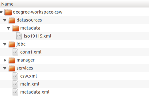
As noted, deegree scans the well-known resource directories for XML files (*.xml) on startup (note that it will omit directory manager, as it is not a well-known resource directory). For every file found, deegree will check the type of configuration format (by determining the name of the XML root element). If it is a recognized format, deegree will try to create and initialize a corresponding resource. For the example, this results in the following setup:
-
A metadata store with id iso19115
-
A JDBC connection pool with id conn1
-
A web service with id csw
The individual XML resource formats and their options are described in the later chapters of the documentation.
|
Tip
|
You may wonder why the main.xml and metadata.xml files are not considered as web service resource files. These two filenames are reserved and treated specifically. See Web services for details. |
|
Tip
|
The configuration format has to match the workspace subdirectory, e.g. metadata store configuration files are only considered when they are located in datasources/metadata. |
4.4.2. Resource identifiers and dependencies
It has already been hinted that resources have an identifier, e.g. for file jdbc/conn1.xml a JDBC connection pool with identifier conn1 is created. You probably have guessed that the identifier is derived from the file name (file name minus suffix), but you may wonder what purpose the identifier serves. The identifier is used for wiring resources. For example, an ISO metadata store resource requires a JDBC pool, because it provides the actual connections to the SQL database. Therefore, the corresponding resource configuration format has an element to specify it:
Example for wiring workspace resources
<ISOMetadataStore configVersion="3.4.0" xmlns="http://www.deegree.org/datasource/metadata/iso19115">

  <!-- [1] Identifier of JDBC connection -->
  <JDBCConnId>conn1</JDBCConnId>

  [...]

</ISOMetadataStore>
In this example, the ISO metadata store is wired to JDBC connection pool conn1. Many deegree resource configuration files contain such references to dependent resources. Some resources perform auto-wiring. For example, every CSW instance needs to connect to a metadata store for accessing stored metadata records. If the CSW configuration omits the reference to the metadata store, it is assumed that there’s exactly one metadata store defined in the workspace and deegree will automatically connect the CSW to this store.
|
Tip
|
The required dependencies are specific to every type of resource and are documented for each resource configuration format. |
4.5. Using the service console for managing resources
As an alternative to dealing with the workspace resource configuration files directly on the filesystem, you can also use the service console for this task. The service console has a corresponding menu entry for every type of workspace resource. All resource menu entries are grouped in the lower menu on the left:
Although the console offers additional functionality for some resource types, the basic management of resources is always identical.
4.5.1. Displaying configured resources
In order to display the configured workspace resources of a certain type, click on the corresponding menu entry. The following screenshot shows the metadata store resources in deegree-workspace-csw:

The right part of the window displays a table with all configured metadata store resources. In this case, the workspace contains a single resource with identifier "iso19115" which is in status "On".
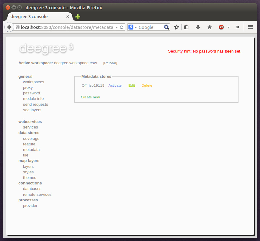
4.5.2. Deactivating a resource
The "Deactivate" link allows to turn off a resource temporarily (while keeping the configuration):
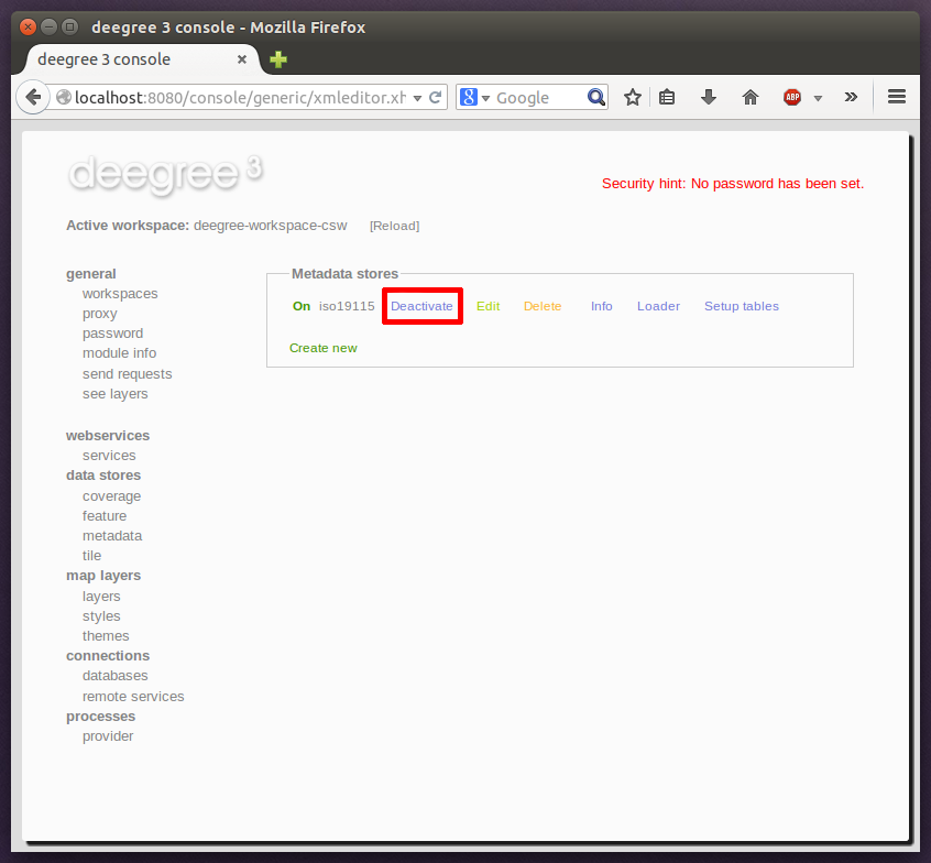
After clicking on "Deactivate", the status of the resource will be "Off", and the "Deactivate" link will change to "Activate". Also, the "Reload" link at the top will turn red to notify that there may be changes that need to be propagated to dependent resources:
|
Tip
|
When a resource is being deactivated, the suffix of the corresponding configuration file is changed to ".ignore". Reactivating changes the suffix back to ".xml". |
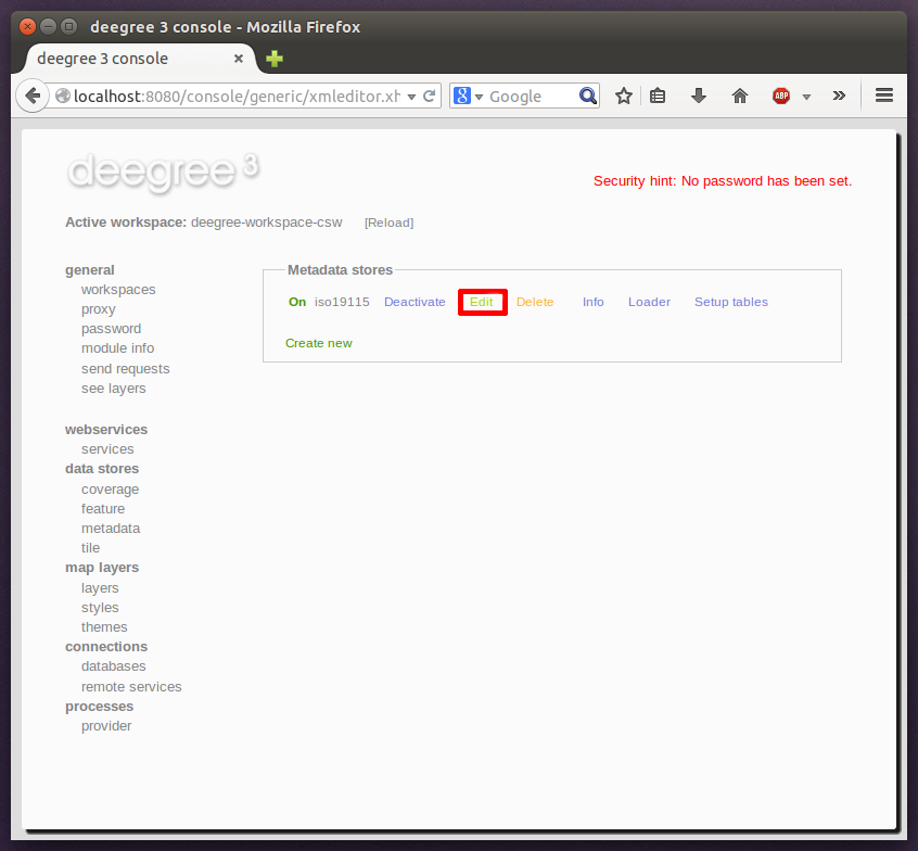
4.5.3. Editing a resource
By clicking on the "Edit" link, you can edit the corresponding XML configuration inside your browser:
The XML configuration will be displayed:
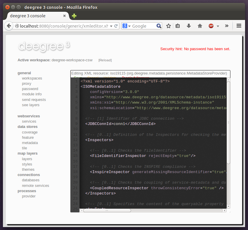
You can now perform configuration changes in the text area and click on "Save". Or click any of the links:
-
Display Schema: Displays the XML schema file for the resource configuration format.
-
Cancel: Discards any changes.
-
Turn on highlighting: Perform syntax highlighting.
If there are no (syntactical) errors in the configuration, the "Save" link will take you back to the corresponding resource view. Before actually saving the file, the service console will perform an XML validation of the file and display any syntactical errors:
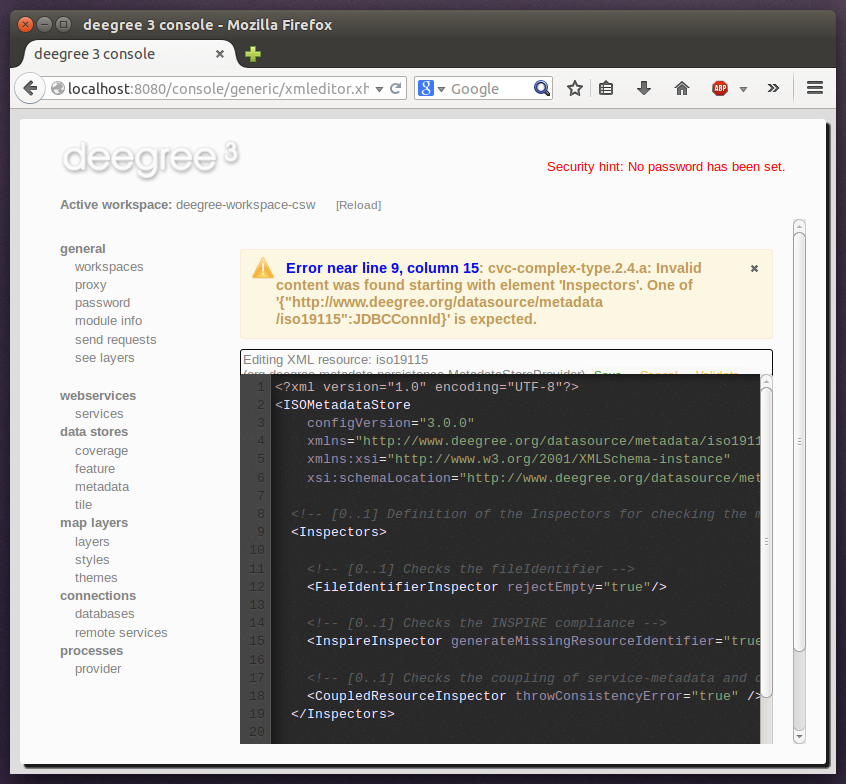
In this case, the mandatory "JDBCConnId" element was removed, which violates the configuration schema. This needs to be corrected, before "Save" will actually save the file to the workspace directory.
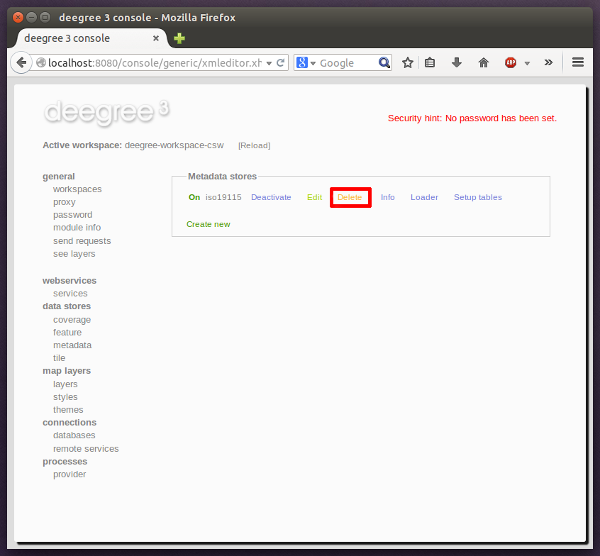
4.5.4. Deleting a resource
The "Delete" link will deactivate the resource and delete the corresponding configuration file from the workspace:
4.5.5. Creating a new resource
In order to add a new resource, enter a new identifier in the text field, select a resource sub-type from the drop-down and click on "Create new":
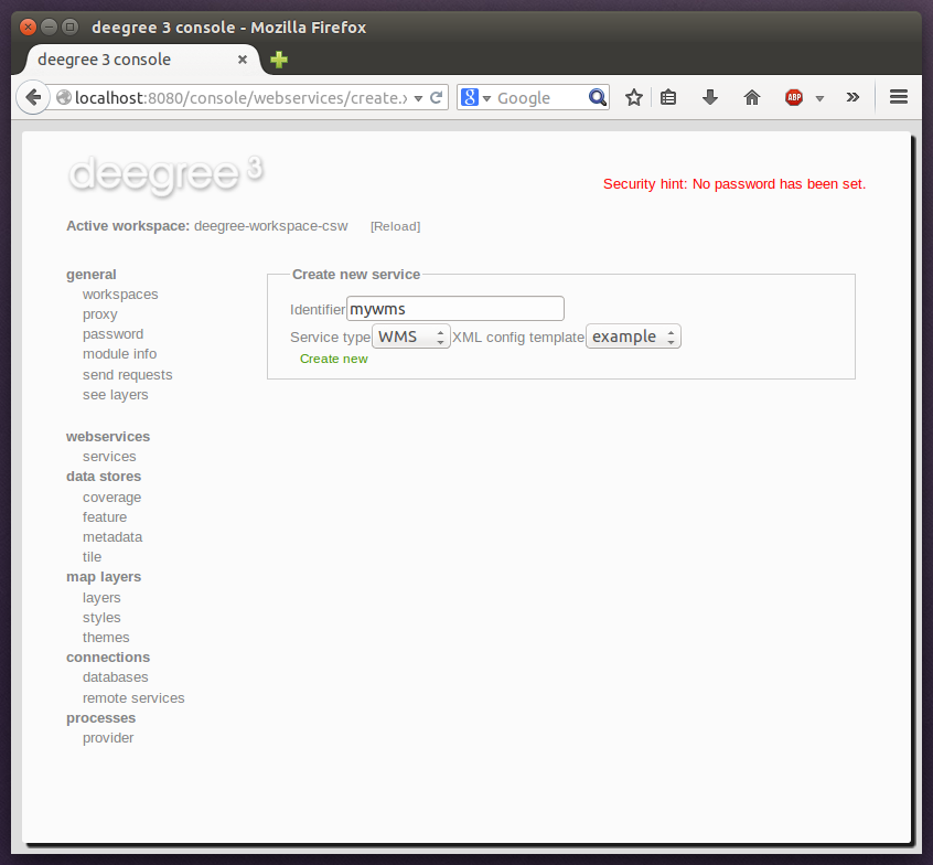
The next steps depend on the type of resource, but generally you have to choose between different options and the result will be a new resource configuration file in the workspace.
4.5.6. Displaying error messages
One of the most helpful features of the console is that it can help to detect and fix errors in a workspace setup. For example, if you delete (or deactivate) JDBC connection "conn1" in deegree-workspace-csw and click "[Reload]", you will see the following:

The red exclamation marks near "services" and "metadata" show that these resource categories have resources with errors. Let’s click on the metadata link to see what’s going on:
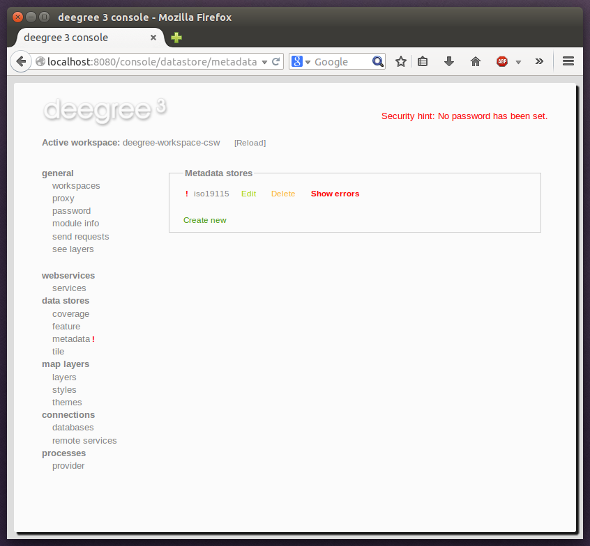
The metadata resource view reveals that the metadata store "iso19115" has an error. Clicking on "Show errors" leads to:
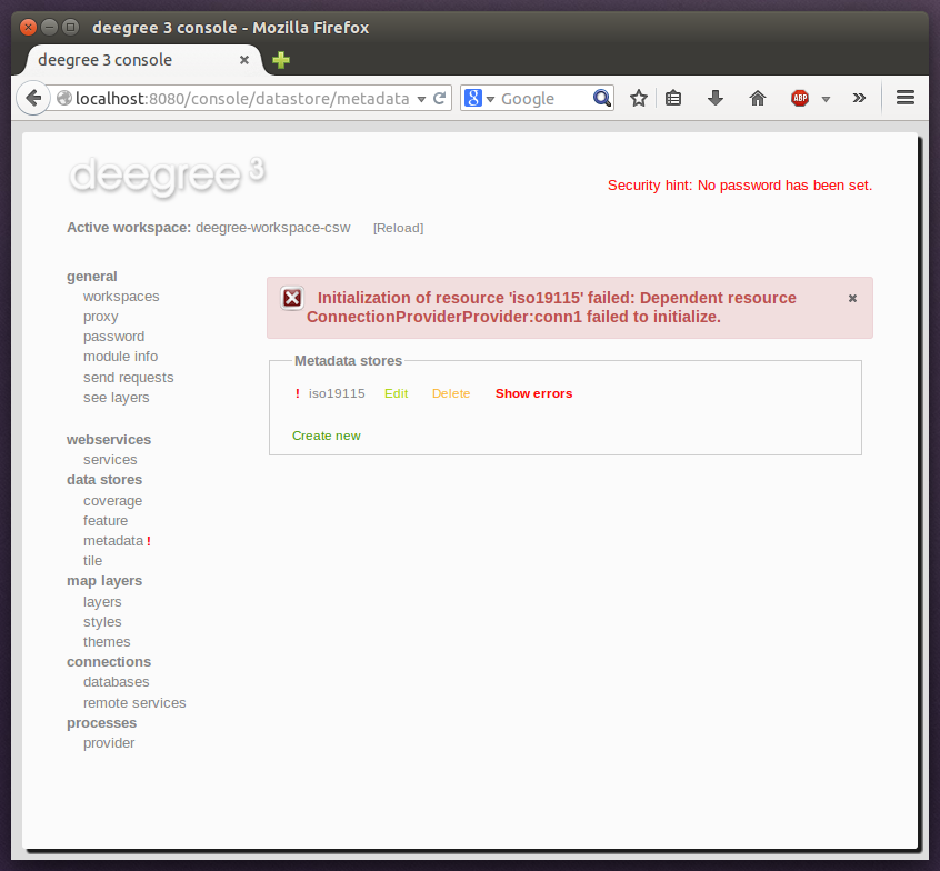
The error message gives an important hint: "No JDBC connection pool with id 'conn1' defined." deegree was unable to initialize the metadata store, because it refers to a JDBC connection pool "conn1". You may wonder what the error in the services category is about:
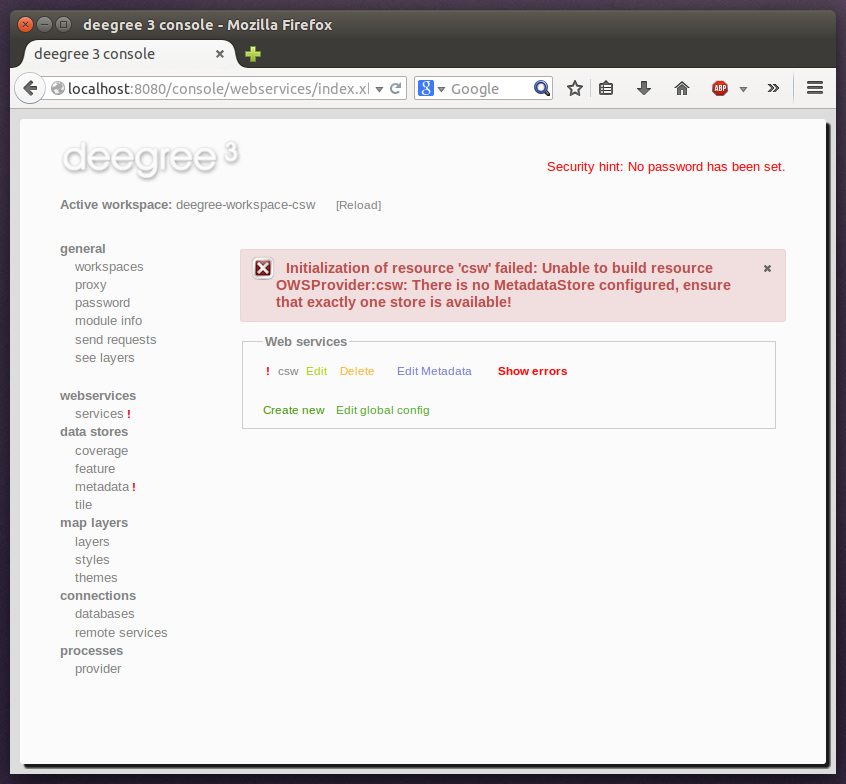
As you see, the problem with the service resource ("There is no MetadataStore configured, ensure that exactly one store is available!) is actually a consequence of the other issue. Because deegree couldn’t initialize the metadata store, it was also unable to start up the CSW correctly. If you add a new JDBC connection "conn1" and click on "[Reload]", both problems should disappear.
4.5.7. Resource type specific actions
In addition to the common management functionality, some resource views offer additional actions. This is described in the corresponding chapters, but here’s a short overview:
-
Web Services: Display service capabilities ("Capabilities"), edit service metadata ("Edit metadata"), edit controller configuration ("Edit global config")
-
Feature Stores: Display feature types and number of stored features ("Info"), Import GML feature collections ("Loader"), Mapping wizard ("Create new" SQL feature store)
-
Metadata Stores: Import metadata sets ("Loader"), create database tables ("Setup tables")
-
Server Connections (JDBC): Test database connection ("Test")
4.6. Best practices for creating workspaces
This section provides some hints for creating a deegree workspace.
4.6.1. Start from example or from scratch
For creating your own workspace, you have two options. Option 1 is to use an existing workspace as a template and adapt it to your needs. Option 2 is to start from scratch, using an empty workspace. Adapting an existing workspace makes a lot of sense if your use-case is close to the scenario of the workspace. For example, if you want to set up INSPIRE View and Download Services, it is a good option to use Example workspace 1: INSPIRE Network Services as a starting point.
In order to create a new workspace, simply create a new directory in the .deegree directory.
Afterwards, switch to the new workspace using the services console, as described in Downloading and activating example workspaces.
4.6.2. Find out which resources you need
The first step is to identify the types of workspace resources that you need for your use-case. You probably know already which types of services your setup requires. The next step is to identify the dependencies for every service by having a look at the respective chapter in the documentation. Let’s say you want a setup with a transactional WFS, a WMS and a CSW:
-
A WFS instance requires 1..n feature stores
-
A WMS instance requires 1..n themes
-
A CSW instance requires a single metadata store
Now you have to dig deeper: What kinds of feature stores exist? Maybe you will find out that what you want is an SQL feature store. So you read the respective part of the documentation and see that an SQL feature store requires a JDBC connection pool resource. Do the same research for the WMS dependencies. A WMS depends on a theme. Find out what a theme is and what it requires. In short, you have to answer the following questions for every encountered resource:
-
What does resource do?
-
How is it configured?
-
On which resources does this resource depend?
At the end of this process you should know about the resources that you will have to configure for your setup.
|
Tip
|
Alternatively, you can approach the resources question bottom-up. Let’s say you have your data ready in a PostGIS database. You want to visualize it using a WMS. So you would require a JDBC resource pool that connects to your database. You need a simple SQL feature store (or an SQL feature store) that uses the new connection pool. You create one or more feature layers that are wired to the feature store and a theme based on the layers. At the end of the chain is the WMS resource which has to be configured to use the theme resource. Rendering styles can be created later (references have to be added to the layers configuration). |
4.6.3. Use a validating XML editor
All deegree XML configuration files have a corresponding XML schema, which allows to detect syntactical errors easily. The editor built into the services console performs validation when you save a configuration file. If the contents is not valid according to the schema, the file will not be saved, but an error message will be displayed:
If you prefer to use a different editor for editing deegree’s configuration files, it is highly recommended to choose a validating XML editor. Successfully tested editors are Eclipse and Altova XML Spy, but any schema-aware editor should work.
|
Tip
|
In case you are able to understand XML schema, you can also use the schema file to find out about the available config options. deegree’s schema files are hosted at http://schemas.deegree.org. |
4.6.4. Check the resource status and error messages
As pointed out in Displaying error messages, the service console indicates errors if resources cannot be initialized. Here’s an example:
In this case, it was not possible to initialize the JDBC connection (and the resources that depend on it). You can spot resource categories and resources that have errors easily, as they have a red exclamation mark. Click on the respective resource level and on "Errors" near the broken resource to see the error message. After fixing the error, click on "Reload" to re-initialize the workspace. If your fix was successful, the exclamation mark will be gone.
Additional information can be found in the deegree log. If you’re running the ZIP version, switch to the terminal window. When initializing workspace resources, information on every resource will be logged, along with error messages.
|
Tip
|
If you deployed the WAR version, the location of the deegree log depends on your web application container. For Tomcat, you will find it in file catalina.out in the log/ directory. |
|
Tip
|
More logging can be activated by adjusting file log4j.properties in the /WEB-INF/classes/ directory of the deegree webapplication. |
5. Web services
This chapter describes the configuration of web service resources. You can access this configuration level by clicking the web services link in the administration console. The corresponding configuration files are located in the services/ subdirectory of the active deegree workspace directory.
|
Tip
|
The identifier of a web service resource has a special purpose. If your deegree instance can be reached at http://localhost:8080/deegree-webservices, the common endpoint for connecting to your services is http://localhost:8080/deegree-webservices/services. However, if you define multiple service resources of the same type in your workspace (e.g. two WMS instances with identifiers wms1 and wms2), you cannot use the common URL, as deegree cannot determine the targeted WMS instance from the request. In this case, simply append the resource identifier to the common endpoint URL (e.g. http://localhost:8080/deegree-webservices/services/wms2) to choose the service resource that you want to connect to explicitly. |
5.1. Web Feature Service (WFS)
A deegree WFS setup consists of a WFS configuration file and any number of feature store configuration files. Feature stores provide access to the actual data (which may be stored in any of the supported backends, e.g. in shapefiles or spatial databases such as PostGIS or Oracle Spatial). In transactional mode (WFS-T), feature stores are also used for modification of stored features:
5.1.1. Minimal example
The only mandatory option is QueryCRS, therefore, a minimal WFS configuration example looks like this:
WFS config example 1: Minimal configuration
<deegreeWFS configVersion="3.4.0"
  xmlns="http://www.deegree.org/services/wfs"
  xmlns:xsi="http://www.w3.org/2001/XMLSchema-instance"
  xsi:schemaLocation="http://www.deegree.org/services/wfs
  http://schemas.deegree.org/services/wfs/3.4.0/wfs_configuration.xsd">

  <QueryCRS>urn:ogc:def:crs:EPSG::4258</QueryCRS>

</deegreeWFS>
This will create a deegree WFS with the feature types from all configured feature stores in the workspace and urn:ogc:def:crs:EPSG::4258 as coordinate system for returned GML geometries.
5.1.2. More complex example
A more complex configuration example looks like this:
WFS config example 2: More complex configuration
<deegreeWFS configVersion="3.4.0"
  xmlns="http://www.deegree.org/services/wfs"
  xmlns:xsi="http://www.w3.org/2001/XMLSchema-instance"
  xsi:schemaLocation="http://www.deegree.org/services/wfs
  http://schemas.deegree.org/services/wfs/3.4.0/wfs_configuration.xsd">

  <SupportedVersions>
    <Version>2.0.0</Version>
    <Version>1.1.0</Version>
  </SupportedVersions>

  <FeatureStoreId>inspire-ad</FeatureStoreId>

  <EnableTransactions idGen="UseExisting">true</EnableTransactions>
  <EnableResponseBuffering>false</EnableResponseBuffering>
  <DisabledResources>
    <Pattern>http://inspire.ec.europa.eu/codelist</Pattern>
  </DisabledResources>

  <SupportedRequests>
    <SupportedEncodings>kvp</SupportedEncodings>
     <GetCapabilities>
      <SupportedEncodings>xml soap</SupportedEncodings>
    </GetCapabilities>
    <DescribeFeatureType/>
    <GetFeature>
      <SupportedEncodings>xml</SupportedEncodings>
    </GetFeature>
  </SupportedRequests>

  <QueryCRS>urn:ogc:def:crs:EPSG::4258</QueryCRS>
  <QueryCRS>urn:ogc:def:crs:EPSG::4326</QueryCRS>
  <QueryMaxFeatures>-1</QueryMaxFeatures>
  <QueryCheckAreaOfUse>false</QueryCheckAreaOfUse>

  <GMLFormat gmlVersion="GML_32">
    <MimeType>application/gml+xml; version=3.2</MimeType>
    <MimeType>text/xml; subtype=gml/3.2.1</MimeType>
    <GenerateBoundedByForFeatures>false</GenerateBoundedByForFeatures>
    <GetFeatureResponse xmlns:gml="http://www.opengis.net/gml/3.2">
      <ContainerElement>gml:FeatureCollection</ContainerElement>
      <FeatureMemberElement>gml:featureMember</FeatureMemberElement>
      <AdditionalSchemaLocation>http://www.opengis.net/gml/3.2 http://schemas.opengis.net/gml/3.2.1/deprecatedTypes.xsd
      </AdditionalSchemaLocation>
      <DisableStreaming>false</DisableStreaming>
      <PrebindNamespace prefix="ad" uri="urn:x-inspire:specification:gmlas:Addresses:3.0"/>
      <PrebindNamespace prefix="base" uri="urn:x-inspire:specification:gmlas:BaseTypes:3.2"/>
      <PrebindNamespace prefix="xlink" uri="http://www.w3.org/1999/xlink"/>
    </GetFeatureResponse>
  </GMLFormat>

</deegreeWFS>
5.1.3. Configuration overview
The deegree WFS config file format is defined by schema file http://schemas.deegree.org/services/wfs/3.4.0/wfs_configuration.xsd. The root element is <deegreeWFS> and the config attribute must be 3.4.0. The following table lists all available configuration options (complex ones contain nested options themselves). When specifiying them, their order must be respected.
| Option | Cardinality | Value | Description |
|---|---|---|---|
SupportedVersions |
0..1 |
Complex |
Activated OGC protocol versions, default: all |
FeatureStoreId |
0..n |
String |
Feature stores to attach, default: all |
EnableTransactions |
0..1 |
Complex |
Enable transactions (WFS-T operations), default: false |
EnableResponseBuffering |
0..1 |
Boolean |
Enable response buffering (expensive), default: false |
DisabledResources |
0..1 |
Complex |
Disables resolve of xlink:href attribute references |
EnableResponsePaging |
0..1 |
Boolean |
Enable response paging (WFS 2.0.0 option), default: false |
SupportedRequests |
0..1 |
Complex |
Configuration of WFS requests |
QueryCRS |
1..n |
String |
Announced CRS, first element is the default CRS |
QueryMaxFeatures |
0..1 |
Integer |
Limit of features returned in a response, default: 15000 |
ResolveTimeOutInSeconds |
0..1 |
Integer |
Expiry time in seconds |
QueryCheckAreaOfUse |
0..1 |
Boolean |
Check spatial query constraints against CRS area, default: false |
StoredQuery |
0..n |
String |
File name of StoredQueryDefinition |
ExtendedCapabilities |
0..n |
String |
Extended Metadata reported in GetCapabilities response |
GMLFormat |
0..n |
Complex |
GML format configuration |
CustomFormat |
0..n |
Complex |
Custom format configuration |
The remainining sections describe these options and their sub-options in detail.
5.1.4. General options
-
SupportedVersions: By default, all implemented WFS protocol versions (1.0.0, 1.1.0 and 2.0.0) will be activated. You can control offered WFS protocol versions using element SupportedVersions. This element allows any combination of the child elements <Version>1.0.0</Version>, <Version>1.1.0</Version> and <Version>2.0.0</Version>.
-
FeatureStoreId: By default, all feature stores in your deegree workspace will be used for serving feature types. In some cases, this may not be what you want, e.g. because you have two different WFS instances running, or you don’t want all feature types used in your WMS for rendering to be available via your WFS. Use the FeatureStoreId option to explicitly set the feature stores that this WFS should use.
-
EnableResponseBuffering: By default, WFS responses are directly streamed to the client. This is very much recommended and even a requirement for transferring large responses efficiently. The only drawback happens if exceptions occur, after a partial response has already been transferred. In this case, the client will receive part payload and part exception report. By specifying true here, you can explicitly force buffering of the full response, before it is written to the client. Only if the full response could be generated successfully, it will be transferred. If an exception happens at any time the buffer will be discarded, and an exception report will be sent to the client. Buffering is performed in memory, but switches to a temp file in case the buffer grows bigger than 1 MiB.
-
DisabledResources: By default all xlink:href attribute references are tried to resolved as feature references during insert. This can be avoided by configuring one or multiple base url patterns within the child element Pattern. Pattern can occur multiple times, one for each base url. In the complex example above resolving of http://inspire.ec.europa.eu/codelist/DesignationSchemeValue/natura2000 and http://inspire.ec.europa.eu/codelist/Natura2000DesignationValue/specialProtectionArea is disabled, but not https://inspire.ec.europa.eu/codelist/DesignationSchemeValue/natura2000 and http://deegree.org/external/feature.
-
EnableResponsePaging: By default, WFS 2.0.0 does not support response paging. By specifying true here, you can explicitly enable response paging. Response Paging works only when streaming is disabled. Currently @next and @previous URLs bases on the original GetFeature request in KVP encoding.
-
QueryCRS: Coordinate reference systems for returned geometries. This element can be specified multiple times, and the WFS will announce all CRS in the GetCapabilities response (except for WFS 1.0.0 which does not officially support using multiple coordinate reference systems). The first element always specifies the default CRS (used when no CRS parameter is present in a request).
-
QueryMaxFeatures: By default, a maximum number of 15000 features will be returned for a single GetFeature request. Use this option to override this setting. A value of -1 means unlimited.
-
ResolveTimeOutInSeconds: Use this option to specify a default value for ResolveTimeOut, used in GetFeature request if the ResolveTimeOut option is not set.
-
QueryCheckAreaOfUse: By default, spatial query constraints are not checked with regard to the area of validity of the CRS. Set this option to true to enforce this check.
5.1.5. Transactions
By default, WFS-T requests will be rejected. Setting the EnableTransactions option to true will enable transaction support. This option has the optional attribute idGenMode which controls how ids of inserted features (the values in the gml:id attribute) are treated. There are three id generation modes available:
-
UseExisting: The original gml:id values from the input are stored. This may lead to errors if the provided ids are already in use.
-
UseExistingResolvingReferencesInternally: Same as UseExisting, but it is allowed to insert features with references to already inserted features.
-
GenerateNew (default): New and unique ids are generated. References in the input GML (xlink:href) that point to a feature with an reassigned id are fixed as well, so reference consistency is maintained.
-
ReplaceDuplicate: The WFS will try to use the original gml:id values that have been provided in the input. In case a certain identifier already exists in the backend, a new and unique identifier will be generated. References in the input GML (xlink:href) that point to a feature with an reassigned id are fixed as well, so reference consistency is maintained.
|
Note
|
Currently, transactions can only be enabled if your WFS is attached to a single feature store. |
|
Note
|
Not every feature store implementation supports transactions, so you may encounter that transactions are rejected, even though you activated them in the WFS configuration. |
|
Note
|
The details of the id generation depend on the feature store implementation/configuration. |
|
Note
|
In a WFS 1.1.0 insert, the id generation mode can be overridden by attribute idGenMode of the Insert element. WFS 1.0.0 and WFS 2.0.0 don’t support to specify the id generation mode on a request basis. |
|
Note
|
When a feature is replaced the UseExisting option is always activated for that transaction. The gml:id of the feature is used for the new version of the feature. The filter is used to identify the feature to be replaced. |
5.1.6. SupportedRequests
This option can be used to configure the supported request types. Currently the supported encodings can be specified for each request type. If the option is missing all encodings are supported for each request type. The option has the following sup-options:
| Option | Cardinality | Value | Description |
|---|---|---|---|
SupportedEncodings |
0..1 |
String |
Enable encodings for all configured request types. Allowed values: 'kvp', 'xml', 'soap'. Multiple values must be separated by a white space. |
GetCapabilities |
0..1 |
Complex |
Configuration of GetCapabilities requests |
DescribeFeatureType |
0..1 |
Complex |
Configuration of DescribeFeatureType requests |
GetFeature |
0..1 |
Complex |
Configuration of GetFeature requests |
Transaction |
0..1 |
Complex |
Configuration of Transaction requests |
GetFeatureWithLock |
0..1 |
Complex |
Configuration of GetFeatureWithLock requests |
GetGmlObject |
0..1 |
Complex |
Configuration of GetGmlObject requests |
LockFeature |
0..1 |
Complex |
Configuration of LockFeature requests |
GetPropertyValue |
0..1 |
Complex |
Configuration of GetPropertyValue requests |
CreateStoredQuery |
0..1 |
Complex |
Configuration of CreateStoredQuery requests |
DropStoredQuery |
0..1 |
Complex |
Configuration of DropStoredQuery requests |
ListStoredQueries |
0..1 |
Complex |
Configuration of ListStoredQueries requests |
DescribeStoredQueries |
0..1 |
Complex |
Configuration of DescribeStoredQueries requests |
Each request type has the following sup-option:
| Option | Cardinality | Value | Description |
|---|---|---|---|
SupportedEncodings |
0..1 |
String |
Enable encodings for this request types. Allowed values: 'kvp', 'xml', 'soap'. Multiple values must be separated by a white space. |
By default deegree will provide all supported request types with all available encodings (kvp, xml, soap).
If a single supported request or encoding is configured, all non configured requests or encodings are disabled.
Example: To limit the provided request types to GetCapabilities and GetFeature this request types can be added without SupportedEncodings sub-option:
<SupportedRequests>
  <GetCapabilities />
  <GetFeature />
</SupportedRequests>
Example: To disable SOAP encoding the other encodings can be added without SupportedRequests sub-option:
<SupportedRequests>
  <SupportedEncodings>kvp xml</SupportedEncodings>
</SupportedRequests>|
Warning
|
It is not checked if the configuration is valid against the WFS specification! |
5.1.7. Adapting GML output formats
By default, a deegree WFS will offer GML 2, 3.0, 3.1, and 3.2 as output formats and announce those formats in the GetCapabilities responses (except for WFS 1.0.0, as this version of the standard has no means of announcing other formats than GML 2). The element for GetFeature responses is wfs:FeatureCollection, as mandated by the WFS specification.
In some cases, you may want to alter aspects of the offered output formats. For example, if you want your WFS to serve a specific application schema (e.g. INSPIRE Data Themes), you should restrict the announced GML versions to the one used for the application schema. These and other output-format related aspects can be controlled by element GMLFormat.
Example for WFS config option GMLFormat
<GMLFormat gmlVersion="GML_32">

  <MimeType>text/xml; subtype=gml/3.2.1</MimeType>

  <GenerateBoundedByForFeatures>false</GenerateBoundedByForFeatures>

  <GetFeatureResponse>
    <ContainerElement xmlns:gml="http://www.opengis.net/gml/3.2">gml:FeatureCollection</ContainerElement>
    <FeatureMemberElement xmlns:gml="http://www.opengis.net/gml/3.2">gml:featureMember</FeatureMemberElement>
    <AdditionalSchemaLocation>
      http://www.opengis.net/gml/3.2 http://schemas.opengis.net/gml/3.2.1/deprecatedTypes.xsd
    </AdditionalSchemaLocation>
    <DisableDynamicSchema>true</DisableDynamicSchema>
    <DisableStreaming>false</DisableStreaming>
    <GeometryLinearization>
      <Accuracy>0.1</Accuracy>
    </GeometryLinearization>
  </GetFeatureResponse>

  <DecimalCoordinateFormatter places="8"/>

</GMLFormat>
The GMLFormat option has the following sub-options:
| Option | Cardinality | Value | Description |
|---|---|---|---|
@gmlVersion |
1..1 |
String |
GML version (GML_2, GML_30, GML_31 or GML_32) |
MimeType |
1..n |
String |
Mime types associated with this format configuration |
GenerateBoundedByForFeatures |
0..1 |
Boolean |
Forces output of gml:boundedBy property for every feature |
GetFeatureResponse |
0..1 |
Complex |
Options for controlling GetFeature responses |
DecimalCoordinateFormatter/ CustomCoordinateFormatter |
0..1 |
Complex |
Controls the formatting of geometry coordinates |
GeometryLinearization |
0..1 |
Complex |
Activates/controls the linearization of exported geometries |
Basic GML format options
-
@gmlVersion: This attribute defines the GML version (GML_2, GML_30, GML_31 or GML_32)
-
MimeType: Mime types associated with this format configuration (and announced in GetCapabilities)
-
GenerateBoundedByForFeatures: By default, the gml:boundedBy property will only be exported for the member features if the feature store provides it. By setting this option to true, the WFS will calculate the envelope and include it as a gml:boundedBy property. Please note that this setting does not affect the inclusion of the gml:boundedBy property for on the feature collection level (see DisableStreaming for that).
GetFeature response settings
Option GetFeatureResponse has the following sub-options:
| Option | Cardinality | Value | Description |
|---|---|---|---|
ContainerElement |
0..1 |
QName |
Qualified root element name, default: wfs:FeatureCollection |
FeatureMemberElement |
0..1 |
QName |
Qualified feature member element name, default: gml:featureMember |
AdditionalSchemaLocation |
0..1 |
String |
Added to xsi:schemaLocation attribute of wfs:FeatureCollection |
DisableDynamicSchema |
0..1 |
Complex |
Controls DescribeFeatureType strategy, default: regenerate schema |
DisableStreaming |
0..1 |
Boolean |
Disables output streaming, include numberOfFeature information/gml:boundedBy |
PrebindNamespace |
0..n |
Complex |
Pre-bind namespaces in the root element |
-
ContainerElement: By default, the container element of a GetFeature response is wfs:FeatureCollection. Using this option, you can specify an alternative element name. In order to bind the namespace prefix, use standard XML namespace mechanisms (xmlns attribute). This option is ignored for WFS 2.0.0.
-
FeatureMemberElement: By default, the member features are included in gml:featureMember (WFS 1.0.0/1.1.0) or wfs:member elements (WFS 2.0.0). Using this option, you can specify an alternative element name. In order to bind the namespace prefix, use standard XML namespace mechanisms (xmlns attribute). This option is ignored for WFS 2.0.0.
-
AdditionalSchemaLocation: By default, the xsi:schemaLocation attribute in a GetFeature response is auto-generated and refers to all schemas necessary for validation of the response. Using this option, you can add additional namespace/URL pairs for adding additional schemas. This may be required when you override the returned container or feature member elements in order to achieve schema-valid output.
-
DisableDynamicSchema: By default, the GML application schema returned in DescribeFeatureType reponses (and referenced in the xsi:schemaLocation of query responses) will be generated dynamically from the internal feature type representation. This allows generation of application schemas for different GML versions and is fine for simple feature models (e.g. feature types served from shapefiles or flat database tables). However, valid re-encoding of complex GML application schema (such as INSPIRE Data Themes) is technically not feasible. In these cases, you will have to set this option to false, so the WFS will produce a response that refers to the original schema files used for configuring the feature store. If you want the references to point to an external copy of your GML application schema files (instead of pointing back to the deegree WFS), use the optional attribute baseURL that this element provides.
-
DisableStreaming: By default, returned features are not collected in memory, but directly streamed from the backend (e.g. an SQL database) and individually encoded as GML. This enables the querying of huge numbers of features with only minimal memory footprint. However, by using this strategy, the number of features and their bounding box is not known when the WFS starts to write out the response. Therefore, this information is omitted from the response (which is perfectly valid according to WFS 1.0.0 and 1.1.0, and a change request for WFS 2.0.0 has been accepted). If you find that your WFS client has problems with the response, you may set this option to false. Features will be collected in memory first and the generated response will include numberOfFeature information and gml:boundedBy for the collection. However, for huge response and heavy server load, this is not recommended as it introduces significant overhead and may result in out-of-memory errors.
-
PrebindNamespace: By default, XML namespaces are bound when they are needed. This will result in valid output, but may lead to the same namespace being bound again and again in different parts of the response document. Using this option, namespaces can be bound in the root element, so they are defined for the full scope of the response document and do not need re-definition at several positions in the document. This
- option has the required attributes prefix and uri. .. note
-
PrebindNamespaces must be configured as in used GML application schemas respectively the imported features (at least for the BLOB mode). It is essential to ensure that prefixes are bound to the same namespace URIs. Otherwise, a GetFeature request may result in a failure ("Duplicate declaration for namespace prefix").
Coordinate formatters
By default, GML geometries will be encoded using 6 decimal places for CRS with degree axes and 3 places for CRS with metric axes. In order to override this, two options are available:
-
DecimalCoordinatesFormatter: Empty element, attribute places specifies the number of decimal places.
-
CustomCoordinateFormatter: By specifiying this element, an implementation of Java interface org.deegree.geometry.io.CoordinateFormatter can be instantiated. Child element JavaClass contains the qualified name of the Java class (which must be on the classpath).
Geometry linearization
Some feature stores (e.g. the SQL feature store when connected to an Oracle Spatial database) can deliver non-linear geometries (e.g. arcs). Here’s an example for the GML 3.1.1 encoding of such a geometry as it would be returned by the WFS:
Example for a non-linear GML geometry
...
<gml:Polygon srsName="urn:ogc:def:crs:EPSG::28992">
  <gml:exterior>
    <gml:Ring srsName="urn:ogc:def:crs:EPSG::28992">
      <gml:curveMember>
        <gml:Curve srsName="urn:ogc:def:crs:EPSG::28992">
          <gml:segments>
            <gml:Arc>
              <gml:posList>240190.182 488008.760 240160.182 487978.760 240190.182 487948.760</gml:posList>
            </gml:Arc>
            <gml:Arc>
              <gml:posList>240190.182 487948.760 240220.182 487978.760 240190.182 488008.760</gml:posList>
            </gml:Arc>
          </gml:segments>
        </gml:Curve>
      </gml:curveMember>
    </gml:Ring>
  </gml:exterior>
</gml:Polygon>
...
This is perfectly valid GML, but there are two reasons why you may not want your WFS to return non-linear GML geometries:
-
There’s no encoding for non-linear GML geometries in GML version 2
-
Currently available WFS clients (e.g. QGIS, uDig, …) cannot cope with them
Option GeometryLinearization will ensure that GML responses will only contain linear geometries. Curves with non-linear segments and surfaces with non-linear boundary segments will be converted before they are encoded to GML. Here’s an example usage of this GML format option:
Example config snippet for activating geometry linearization
...
<GeometryLinearization>
  <Accuracy>0.1</Accuracy>
</GeometryLinearization>
...
GeometryLinearization has a single mandatory option Accuracy. It defines the numerical accuracy of the linear approximation in units of the coordinate reference system used by the feature store. If the coordinate reference system is based on meters, a value of 0.1 will ensure that the maximum error between the original and the linearized geometry does not exceed 10 centimeters.
Here’s an example of a linearized version of the example geometry as it would be generated by the WFS:
Example for linearized GML output
...
<gml:Polygon srsName="urn:ogc:def:crs:EPSG::28992">
  <gml:exterior>
    <gml:Ring srsName="urn:ogc:def:crs:EPSG::28992">
      <gml:curveMember>
        <gml:Curve srsName="urn:ogc:def:crs:EPSG::28992">
          <gml:segments>
            <gml:LineStringSegment interpolation="linear">
              <gml:posList>240190.182 488008.760 240177.165 488005.789 240166.727 487997.465 240160.934 487985.436 240160.934 487972.084 240166.727 487960.055 240177.165 487951.731 240190.182 487948.760</gml:posList>
            </gml:LineStringSegment>
            <gml:LineStringSegment interpolation="linear">
              <gml:posList>240190.182 487948.760 240203.199 487951.731 240213.637 487960.055 240219.430 487972.084 240219.430 487985.436 240213.637 487997.465 240203.199 488005.789 240190.182 488008.760</gml:posList>
            </gml:LineStringSegment>
          </gml:segments>
        </gml:Curve>
      </gml:curveMember>
    </gml:Ring>
  </gml:exterior>
</gml:Polygon>
...
5.1.8. Adding custom output formats
Using option element CustomFormat, it is possible to plug-in your own Java classes to generate the output for a specific mime type (e.g. a binary format)
| Option | Cardinality | Value | Description |
|---|---|---|---|
MimeType |
1..n |
String |
Mime types associated with this format configuration |
JavaClass |
1..1 |
String |
Qualified Java class name |
Config |
0..1 |
Complex |
Value to add to xsi:schemaLocation attribute |
-
MimeType: Mime types associated with this format configuration (and announced in GetCapabilities)
-
JavaClass: Therefore, an implementation of interface org.deegree.services.wfs.format.CustomFormat must be present on the classpath.
-
Config:
5.1.9. Stored queries
Besides standard ('ad hoc') queries, WFS 2.0.0 introduces so-called stored queries. When WFS 2.0.0 support is activated, your WFS will automatically support the well-known stored query urn:ogc:def:storedQuery:OGC-WFS::GetFeatureById (defined in the WFS 2.0.0 specification). It can be used to query a feature instance by specifying it’s gml:id (similar to GetGmlObject requests in WFS 1.1.0). In order to define custom stored queries, use the StoredQuery element to specify the file name of a StoredQueryDefinition file. The given file name (can be relative) must point to a valid WFS 2.0.0 StoredQueryDefinition file. Here’s an example:
Example for a WFS 2.0.0 StoredQueryDefinition file
<StoredQueryDefinition id="urn:x-inspire:query:GetAddressesForStreet"
  xmlns="http://www.opengis.net/wfs/2.0"
  xmlns:ad="urn:x-inspire:specification:gmlas:Addresses:3.0"
  xmlns:gn="urn:x-inspire:specification:gmlas:GeographicalNames:3.0">
  <Title>GetAddressesForStreet</Title>
  <Abstract>Returns the ad:Address features located in the specified street.</Abstract>
  <Parameter name="streetName" type="xs:string">
    <Abstract>Name of the street (mandatory)</Abstract>
  </Parameter>
  <QueryExpressionText returnFeatureTypes="ad:Address"
   language="urn:ogc:def:queryLanguage:OGC-:WFSQueryExpression">
    <Query typeNames="ad:Address">
      <Filter xmlns="http://www.opengis.net/fes/2.0">
        <PropertyIsEqualTo>
          <ValueReference>
ad:component/ad:ThoroughfareName/ad:name/gn:GeographicalName/gn:spelling/gn:SpellingOfName/gn:text
          </ValueReference>
          <Literal>${streetName}</Literal>
        </PropertyIsEqualTo>
      </Filter>
    </Query>
  </QueryExpressionText>
</StoredQueryDefinition>
This example is actually usable if your WFS is set up to serve the ad:Address feature type from INSPIRE Annex I. It defines the stored query urn:x-inspire:storedQuery:GetAddressesForStreet for retrieving ad:Address features that are located in the specified street. The street name is passed using parameter streetName. If your WFS instance can be reached at http://localhost:8080/services, you could use the request http://localhost:8080/services?request=GetFeature&storedquery_id=urn:x-inspire:storedQuery:GetAddressesForStreet&streetName=Madame%20Curiestraat to fetch the ad:Address features in street Madame Curiestraat.
The attribute returnFeatureTypes of QueryExpressionText can be left empty. If this is the case, the element will be filled with all feature types served by the WFS when executing a DescribeStoredQueries request. The same applies for the value $\{deegreewfs:ServedFeatureTypes}. If a value is set for returnFeatureTypes, the user is responsible to configure it as expected: Usually values of the typeNames of the Query-Elements should be used. An exception is thrown as DescribeStoredQueries response, if the configured feature type is not served by the WFS.
To enable support for the Manage Stored Queries conformance class for WFS 2.0.0 it is required to create a directory storedqueries/managed in your workspace. The stored queries created with CreateStoredQuery requests are stored in this directory. They are loaded during startup of deegree automatically. It is not recommend to put the StoredQueries configured in the WFS configuration with the StoredQuery element into this folder. If the directory is missing the CreateStoredQuery request returns an exception.
|
Tip
|
deegree WFS supports the execution of stored queries using GetFeature and GetPropertyValue requests. It also implements the ListStoredQueries, DescribeStoredQueries, CreateStoredQuery and the DropStoredQuery operations. |
5.1.10. Extended capabilities
Important for applications like INSPIRE, it is often desirable to include predefined blocks of XML in the extended capabilities section of the WFS capabilities output. This can be achieved simply by adding these blocks to the extended capabilities element of the configuration:
<ExtendedCapabilities>
  <MyCustomOutput xmlns="http://www.custom.org/output">
    ...
  </MyCustomOutput>
</ExtendedCapabilities>
You must set the attribute wfsVersions to indicate the version that you want to define the extended capabilities for. If your service supports multiple protocol versions (e.g. a WFS that supports 1.1.0 and 2.0.0), you may include multiple ExtendedCapabilities elements in the metadata configuration.
|
Warning
|
The extended capabilities set in the WFS service configuration are ignored, if a metadata configuration file (see chapter Metadata) exists. Instead, the extended capabilities must be configured there. |
5.2. Web Map Service (WMS)
In deegree terminology, a deegree WMS renders maps from data stored in feature, coverage and tile stores. The WMS is configured using a layer structure, called a theme. A theme can be thought of as a collection of layers, organized in a tree structure. What the layers show is configured in a layer configuration, and how it is shown is configured in a style file. Supported style languages are StyledLayerDescriptor (SLD) and Symbology Encoding (SE).
|
Tip
|
In order to fully understand deegree WMS configuration, you will have to learn configuration of other workspace aspects as well. Chapter Map styles describes the creation of layers and styling rules. Chapter Feature stores describes the configuration of vector data access and chapter Coverage stores describes the configuration of raster data access. |
5.2.1. A word on layers and themes
Readers familiar with the WMS protocol might be wondering why layers can not be configured directly in the WMS configuration file. Inspired by WMTS 1.0.0 we found the idea to separate structure and content very appealing. Thinking of a layer store that just offers a set of layers is an easy concept. Thinking of a theme as a structure that may contain layers at certain points also makes sense. But when thinking of WMS the terms begin clashing. We suggest to avoid confusion as much as possible by using the same name for each corresponding theme, layer and possibly even tile/feature/coverage data sources. We believe that once you work a little with the concept of themes, and seeing them exported as WMS layer trees, the concepts fit well enough so you can appreciate the clean cut.
5.2.2. Configuration overview
The configuration can be split up in six sections. Readers familiar with other deegree service configurations may recognize some similarities, but we’ll describe the options anyway, because there may be subtle differences. A document template looks like this:
<?xml version='1.0'?>
<deegreeWMS xmlns='http://www.deegree.org/services/wms'>
  <!-- actual configuration goes here -->
</deegreeWMS>
The following table shows what top level options are available.
| Option | Cardinality | Value | Description |
|---|---|---|---|
SupportedVersions |
0..1 |
Complex |
Limits active OGC protocol versions |
SupportedRequests |
0..1 |
Complex |
Configuration of WMS requests |
UpdateSequence |
0..1 |
Integer |
Current update sequence, default: 0 |
MetadataStoreId |
0..1 |
String |
Configures a metadata store to check if metadata ids for layers exist |
MetadataURLTemplate |
0..1 |
String |
Template for generating URLs to feature type metadata |
ServiceConfiguration |
1 |
Complex |
Configures service content |
GetCapabilitiesFormats |
0..1 |
Complex |
Configures additional capabilities output formats |
FeatureInfoFormats |
0..1 |
Complex |
Configures additional feature info output formats |
GetMapFormats |
0..1 |
Complex |
Configures additional image output formats |
ExceptionFormats |
0..1 |
Complex |
Configures additional exception output formats |
ExtendedCapabilities |
0..n |
Complex |
Extended Metadata reported in GetCapabilities response |
LayerLimit |
0..1 |
Integer |
Maximum number of layers in a GetMap request, default: unlimited |
MaxWidth |
0..1 |
Integer |
Maximum width in a GetMap request, default: unlimited |
MaxHeight |
0..1 |
Integer |
Maximum height in a GetMap request, default: unlimited |
5.2.3. Basic options
-
SupportedVersions: By default, all implemented WMS protocol versions (1.1.1 and 1.3.0) are activated. You can control offered WMS protocol versions using the element SupportedVersions. This element allows any of the child elements <Version>1.1.1</Version> and <Version>1.3.0</Version>.
-
MetadataStoreId: If set to a valid metadata store, the store is queried upon startup with all configured layer metadata set ids. If a metadata set does not exist in the metadata store, it will not be exported as metadata URL in the capabilties. This is a useful option if you want to automatically check for configuration errors/typos. By default, no checking is done.
-
MetadataURLTemplate: By default, no metadata URLs are generated for layers in the capabilities. You can set this option either to a unique URL, which will be exported as is, or to a template with a placeholder. In any case, a metadata URL will only be exported if the layer has a metadata set id set. A template looks like this: http://discovery.eu/csw?service=CSW&request=GetRecordById&version=2.0.2&id=$%7BmetadataSetId%7D&outputSchema=http://www.isotc211.org/2005/gmd&elementSetName=full. Please note that you’ll need to escape the & symbols with & as shown in the example. The ${metadataSetId} will be replaced with the metadata set id from each layer.
Here is a snippet for quick copy & paste:
<SupportedVersions>
<Version>1.1.1</Version>
</SupportedVersions>
<MetadataStoreId>mdstore</MetadataStoreId>
<MetadataURLTemplate>http://discovery.eu/csw?service=CSW&request=GetRecordById&version=2.0.2&id=${metadataSetId}&outputSchema=http://www.isotc211.org/2005/gmd&elementSetName=full</MetadataURLTemplate>5.2.4. SupportedRequests
This option can be used to configure the supported request types. Currently, the supported encodings can be specified for each request type. If the option is missing, all encodings are supported for each request type. The option has the following sup-options:
| Option | Cardinality | Value | Description |
|---|---|---|---|
SupportedEncodings |
0..1 |
String |
Enable encodings for all configured request types. Allowed values: 'kvp', 'xml', 'soap'. Multiple values must be separated by a white space. |
GetCapabilities |
0..1 |
Complex |
Configuration of GetCapabilities requests |
GetMap |
0..1 |
Complex |
Configuration of GetMap requests |
GetFeatureInfo |
0..1 |
Complex |
Configuration of GetFeatureInfo requests |
DescribeLayer |
0..1 |
Complex |
Configuration of DescribeLayer requests |
GetLegendGraphic |
0..1 |
Complex |
Configuration of GetLegendGraphic requests |
GetFeatureInfoSchema |
0..1 |
Complex |
Configuration of GetFeatureInfoSchema requests |
DTD |
0..1 |
Complex |
Configuration of DTD requests |
Each request type has the following sup-option:
| Option | Cardinality | Value | Description |
|---|---|---|---|
SupportedEncodings |
0..1 |
String |
Enable encodings for this request types. Allowed values: 'kvp', 'xml', 'soap'. Multiple values must be separated by a white space. |
By default deegree will provide all supported request types with all available encodings (kvp, xml, soap).
If a single supported request or encoding is configured, all non configured requests or encodings are disabled.
Example: To limit the provided request types to GetCapabilities and GetFeature this request types can be added without SupportedEncodings sub-option:
<SupportedRequests>
  <GetCapabilities />
  <GetFeature />
</SupportedRequests>
Example: To disable SOAP encoding the other encodings can be added without SupportedRequests sub-option:
<SupportedRequests>
  <SupportedEncodings>kvp xml</SupportedEncodings>
</SupportedRequests>|
Warning
|
It is not checked if the configuration is valid against the WMS specification! |
|
Warning
|
WMS 1.1.1 just supports KVP. SOAP can only be used for GetCapabilities, GetMap and GetFeatureInfo operations of WMS 1.3.0. Nevertheless, configuration of all combinations is possible. |
5.2.5. Service content configuration
You can configure the behaviour of layers using the DefaultLayerOptions element.
Have a look at the layer options and their values:
| Option | Cardinality | String | Description |
|---|---|---|---|
Antialiasing |
0..1 |
String |
Whether to antialias NONE, TEXT, IMAGE or BOTH, default is BOTH |
RenderingQuality |
0..1 |
String |
Whether to render LOW, NORMAL or HIGH quality, default is HIGH |
Interpolation |
0..1 |
String |
Whether to use BILINEAR, NEARESTNEIGHBOUR or BICUBIC interpolation, default is NEARESTNEIGHBOUR |
MaxFeatures |
0..1 |
Integer |
Maximum number of features to render at once, default is 10000 |
FeatureInfoRadius |
0..1 |
Integer |
Number of pixels to consider when doing GetFeatureInfo, default is 1 |
Opaque |
0..1 |
Boolean |
Indicates if the map data of the layer are mostly or completely opaque (true) or represents vector features that probably do not completely fill space (false), default is false |
You can configure the WMS to use one or more preconfigured themes. In WMS terms, each theme is mapped to a layer in the WMS capabilities. So if you use one theme, the WMS root layer corresponds to the root theme. If you use multiple themes, a synthetic root layer is exported in the capabilities, with one child layer corresponding to each root theme. The themes are configured using the ThemeId element.
Here is an example snippet of the content section:
<ServiceConfiguration>

  <DefaultLayerOptions>
    <Antialiasing>NONE</Antialiasing>
  </DefaultLayerOptions>

  <ThemeId>mytheme</ThemeId>

</ServiceConfiguration>
5.2.6. Custom capabilities formats
Any mime type can be configured to be available as response format for GetCapabilities requests, although the most commonly used is probably text/html. A XSLT script is used to generate the output.
This is how the configuration section looks like:
<GetCapabilitiesFormats>
  <GetCapabilitiesFormat>
    <XSLTFile>capabilities2html.xsl</XSLTFile>
    <Format>text/html</Format>
  </GetCapabilitiesFormat>
</GetCapabilitiesFormats>
Of course it is possible to define as many custom formats as you want, as long as you use a different mime type for each (just duplicate the GetCapabilitiesFormat element). If you use one of the default formats, the default output will be overridden with your configuration.
5.2.7. Custom feature info formats
Any mime type can be configured to be available as response format for GetFeatureInfo requests, although the most commonly used is probably text/html. There are two alternative ways of controlling how the output is generated (besides using the default HTML output). One involves a deegree specific templating mechanism, the other involves writing an XSLT script. The deegree specific mechanism has the advantage of being considerably less verbose, making common use cases very easy, while the XSLT approach gives you all the freedom.
This is how the configuration section looks like for configuring a deegree templating based format:
<FeatureInfoFormats>
  <GetFeatureInfoFormat>
    <File>../customformat.gfi</File>
    <Format>text/html</Format>
    <Property name="customname" value="customvalue" />
  </GetFeatureInfoFormat>
</FeatureInfoFormats>
The configuration for the XSLT approach looks like this:
<FeatureInfoFormats>
  <GetFeatureInfoFormat>
    <XSLTFile gmlVersion="GML_32">../customformat.xsl</XSLTFile>
    <Format>text/html</Format>
    <Property name="customname" value="customvalue" />
  </GetFeatureInfoFormat>
</FeatureInfoFormats>
Of course it is possible to define as many custom formats as you want, as long as you use a different mime type for each (just duplicate the GetFeatureInfoFormat element). If you use one of the default formats, the default output will be overridden with your configuration.
In order to write your XSLT script, you’ll need to develop it against a specific GML version (namespaces between GML versions may differ, GML output itself will differ). The default is GML 3.2, you can override it by specifying the gmlVersion attribute on the XSLTFile element. Valid GML version strings are GML_2, GML_30, GML_31 and GML_32.
If you want to learn more about the templating format, read the following sections.
5.2.8. FeatureInfo templating format
The templating format can be used to create text based output formats for featureinfo output. It uses a number of definitions, rules and special constructs to replace content with other content based on feature and property values. Please note that you should make sure your file is UTF-8 encoded if you’re using umlauts.
Introduction/Example
This section gives a quick overview how the format works and demonstrates the development of a small sample HTML output.
On top level, you can have a number of template definitions. A template always has a name, and there always needs to be a template named start (yes, it’s the one we start with).
A simple valid templating file that does not actually depend on the features coming in looks like this:
<?template start>
<html>
<body>
  <p>Hello</p>
</body>
</html>
A featureinfo request will now always yield the body of this template. In order to use the features coming in, you need to define other templates, and call them from a template. So let’s add another template, and call it from the start template:
<?template start>
<html>
<body>
<ul>
<?feature *:myfeaturetemplate>
</ul>
</body>
</html>

<?template myfeaturetemplate>
<li>I have a feature</li>
What happens now is that first the body of the start template is being output. In that output, the <?feature *:myfeaturetemplate> is replaced with the content of the myfeaturetemplate template for each feature in the feature collection. So if your query hits five features, you’ll get five li tags like in the template. The asterisk is used to select all features, it’s possible to limit the number of objects matched. See below in the reference section for a detailed explanation on how it works.
Within the myfeaturetemplate template you have switched context. In the start template your context is the feature collection, and you can call feature templates. In the myfeaturetemplate you 'went down' the tree and are now in a feature context, where you can call property templates. So what can we do in a feature context? Let’s start simple by writing out the feature type name. Change the myfeaturetemplate like this:
<?template myfeaturetemplate>
<li>I have a <?name> feature</li>
What happens now is that for each use of the myfeaturetemplate the <?name> part is being replaced with the name of the feature type of the feature you hit. So if you hit two features, each of a different type, you get two different li tags in the document, each with its name written in it.
So deegree only replaces the template call in the start template with its replacement once the special constructs in the called template are all replaced, and all the special constructs/calls within that template are all replaced, … and so on.
Let’s take it to the next level. What’s you really want to do in featureinfo responses is of course get the value of the features' properties. So let’s add another template, and call it from the myfeaturetemplate template:
<?template myfeaturetemplate>
<li>I have a <?name> feature and properties: <?property *:mypropertytemplate></li>

<?template mypropertytemplate>
<?name>=<?value>
Now you also get all property names and values in the li item. Note that again you switched the context in the template, now you are at property level. The <?name> and <?value> special constructs yield the property name and value, respectively (remember, we’re at property level here).
While that’s already nice, people often put non human readable values in properties, even property names are sometimes not human readable. In order to fix that, you often have code lists mapping the codes to proper text. To use these, there’s a special kind of template called a map. A map is like a simple property file. Let’s have a look at how to define one:
<?map mycodelistmap>
code1=Street
code2=Highway
code3=Railway

<?map mynamecodelistmap>
tp=Type of way
Looks simple enough. Instead of template we use map, after that comes the name. Then we just map codes to values. So how do we use this? Instead of just using the <?name> or <?value> we push it through the map:
<?template mypropertytemplate>
<?name:map mynamecodelistmap>=<?value:map mycodelistmap>
Here the name of the property is replaced with values from the mynamecodelistmap, the value is replaced with values from the mycodelistmap. If the map does not contain a fitting mapping, the original value is used instead.
That concludes the introduction, the next section explains all available special constructs in detail.
Templating special constructs
This section shows all available special constructs. The selectors are explained in the table below. The validity describes in which context the construct can be used (and where the description applies). The validity can be one of top level (which means it’s the definition of something), featurecollection (the start template), feature (a template on feature level), property (a template on property level) or map (a map definition).
| Construct | Validity | Description |
|---|---|---|
<?template _name>_ |
top level |
defines a template with name name |
<?map _name>_ |
top level |
defines a map with name name |
<?feature selector:__name_>_ |
featurecollection |
calls the template with name name for features matching the selector selector |
<?property selector:__name_>_ |
feature |
calls the template with name name for properties matching the selector selector |
<?name> |
feature |
evaluates to the feature type name |
<?name> |
property |
evaluates to the property name |
<?name:map _name>_ |
feature |
uses the map name to map the feature type name to a value |
<?name:map _name>_ |
property |
uses the map name to map the property name to a value |
<?value> |
property |
evaluates to the property’s value |
<?value:map _name>_ |
property |
uses the map name to map the property’s value to another value |
<?index> |
feature |
evaluates to the index of the feature (in the list of matches from the previous template call) |
<?index> |
property |
evaluates to the index of the property (in the list of matches from the previous template call) |
<?gmlid> |
feature |
evaluates to the feature’s gml:id |
<?odd:__name_>_ |
feature |
calls the name template if the index of the current feature is odd |
<?odd:__name_>_ |
property |
calls the name template if the index of the current property is odd |
<?even:__name_>_ |
feature |
calls the name template if the index of the current feature is even |
<?even:__name_>_ |
property |
calls the name template if the index of the current property is even |
<?link:_prefix_:> |
property |
if the value of the property is not an absolute link, the prefix is prepended |
<?link:_prefix_:__text_>_ |
property |
the text of the link will be text instead of the link address |
The selector for properties and features is a kind of pattern matching on the object’s name.
| Selector | Description |
|---|---|
* |
matches all objects |
* text |
matches all objects with names ending in text |
text * |
matches all objects with names starting with text |
not(selector) |
matches all objects not matching the selector selector |
selector1, selector2 |
matches all objects matching selector1 and selector2 |
5.2.9. Custom image output formats
Any mime type of the following output formats can be configured to be available as response format for GetMap requests.
-
image/png
-
image/png; subtype=8bit
-
image/png; mode=8bit
-
image/gif
-
image/jpeg
-
image/tiff
-
image/x-ms-bmp
If no format has been configured, all formats are supported.
This is how the configuration section looks like for configuring only image/png as image output format:
<GetMapFormats>
  <GetMapFormat>image/png</GetMapFormat>
</GetMapFormats>
Custom format provider class
Using option element CustomGetMapFormat, it is possible to plug-in your own Java classes to generate the output for a specific mime type
| Option | Cardinality | Value | Description |
|---|---|---|---|
Format |
1..1 |
String |
Mime type associated with this format configuration |
JavaClass |
1..1 |
String |
Qualified Java class name |
Property |
0..n |
Complex |
Configure properties of the JavaClass |
-
Format: Mime type associated with this format configuration (and announced in GetCapabilities)
-
JavaClass: Therefore, an implementation of interface org.deegree.rendering.r2d.ImageSerializer must be present on the classpath.
-
Property:
This is how the configuration looks like for the implementation of GeoTIFF:
<GetMapFormats>
  <CustomGetMapFormat>
    <Format>image/tiff</Format>
    <JavaClass>org.deegree.services.wms.controller.plugins.ImageSerializerGeoTiff</JavaClass>
  </CustomGetMapFormat>
</GetMapFormats>
5.2.10. Custom exception formats
Any mime type can be configured to be available as response format for Exceptions, although the most commonly used is probably text/html. A XSLT script is used to generate the output.
This is how the configuration section looks like:
<ExceptionFormats>
  <ExceptionFormat>
    <XSLTFile>exception2html.xsl</XSLTFile>
    <Format>text/html</Format>
  </ExceptionFormat>
</ExceptionFormats>
Of course it is possible to define as many custom formats as you want, as long as you use a different mime type for each (just duplicate the ExceptionFormat element). If you use one of the default formats, the default output will be overridden with your configuration.
5.2.11. Extended capabilities
Important for applications like INSPIRE, it is often desirable to include predefined blocks of XML in the extended capabilities section of the WMS capabilities output. This can be achieved simply by adding these blocks to the extended capabilities element of the configuration:
<ExtendedCapabilities>
  <MyCustomOutput xmlns="http://www.custom.org/output">
    ...
  </MyCustomOutput>
</ExtendedCapabilities>|
Warning
|
The extended capabilities set in the WMS service configuration are ignored, if a metadata configuration file (see chapter Metadata) exists. Instead, the extended capabilities must be configured there. |
|
Warning
|
Extended Capabilities are currently not supported by WMS 1.1.1. In WMS 1.1.1 configured extended capabilities are ignored and not included in the capabilities document. |
5.2.12. Vendor specific parameters
The deegree WMS supports a number of vendor specific parameters. Some parameters are supported on a per layer basis while some are applied to the whole request. Most of the parameters correspond to the layer options above.
The parameters which are supported on a per layer basis can be used to set an option globally, eg. …&REQUEST=GetMap&ANTIALIAS=BOTH&…, or for each layer separately (using a comma separated list): …&REQUEST=GetMap&ANTIALIAS=BOTH,TEXT,NONE&LAYERS=layer1,layer2,layer3&… Most of the layer options have a corresponding parameter with a similar name: ANTIALIAS, INTERPOLATION, QUALITY and MAX_FEATURES. The feature info radius can currently not be set dynamically.
The PIXELSIZE parameter can be used to dynamically adjust the resolution of the resulting image. The default is the WMS default of 0.28 mm. So to achieve a double resolution, you can double the WIDTH/HEIGHT parameter values and set the PIXELSIZE parameter to 0.14.
Using the QUERYBOXSIZE parameter you can include features when rendering that would normally not intersect the envelope specified in the BBOX parameter. That can be useful if you have labels at point symbols out of the envelope which would be rendered partly inside the map. Normal GetMap behaviour will exclude such a label. With the QUERYBOXSIZE parameter you can specify a factor by which to enlarge the original bounding box, which is used solely for querying the data store (the actual extent returned will not be changed!). Use values like 1.1 to enlarge the envelope by 5% in each direction (this would be 10% in total).
5.2.13. XML request encoding
A WMS 1.3.0 can be requested by HTTP POST (without any KVP) containing XML in request body. The provided XML has to be compliant to a specific XML schema depending on the requested operation.
The operations GetCapabilities, GetMap and GetFeatureInfo support XML request encoding.
GetCapabilities
The GetCapabilities XML request body has to be compliant to following schema:
GetCapabilities XML request body example (can be used with Utah example workspace)
<GetCapabilities xmlns="http://www.opengis.net/ows/2.0" xmlns:xsi="http://www.w3.org/2001/XMLSchema-instance"
  xsi:schemaLocation="http://www.opengis.net/ows/2.0 http://schemas.opengis.net/ows/2.0/owsGetCapabilities.xsd"/>
GetMap
The GetMap XML request body has to be compliant to following schema:
GetMap XML request body example (can be used with Utah example workspace)
<?xml version="1.0" encoding="UTF-8"?>
<GetMap xmlns="http://www.opengis.net/sld" xmlns:ows="http://www.opengis.net/ows" xmlns:se="http://www.opengis.net/se"
  xmlns:wms="http://www.opengis.net/wms" xmlns:xsi="http://www.w3.org/2001/XMLSchema-instance"
  xsi:schemaLocation="http://www.opengis.net/sld http://schemas.opengis.net/sld/1.1/GetMap.xsd" version="1.3.0">
  <StyledLayerDescriptor version="1.1.0">
    <NamedLayer>
      <se:Name>municipalities</se:Name>
      <NamedStyle>
        <se:Name>Municipalities</se:Name>
      </NamedStyle>
    </NamedLayer>
    <NamedLayer>
      <se:Name>counties</se:Name>
      <NamedStyle>
        <se:Name>CountyBoundary</se:Name>
      </NamedStyle>
    </NamedLayer>
    <NamedLayer>
      <se:Name>zipcodes</se:Name>
      <NamedStyle>
        <se:Name>default</se:Name>
      </NamedStyle>
    </NamedLayer>
  </StyledLayerDescriptor>
  <CRS>EPSG:4326</CRS>
  <BoundingBox crs="http://www.opengis.net/gml/srs/epsg.xml#4326">
    <ows:LowerCorner>-115.4 35.0</ows:LowerCorner>
    <ows:UpperCorner>-108.0 44.0</ows:UpperCorner>
  </BoundingBox>
  <Output>
    <Size>
      <Width>1024</Width>
      <Height>512</Height>
    </Size>
    <wms:Format>image/png</wms:Format>
    <Transparent>true</Transparent>
  </Output>
  <Exceptions>XML</Exceptions>
</GetMap>
GetFeatureInfo
The GetFeatureInfo XML request body has to be compliant to following schema:
<?xml version="1.0" encoding="UTF-8"?>
<xs:schema targetNamespace="http://www.opengis.net/ows"
  xmlns:xs="http://www.w3.org/2001/XMLSchema"
  xmlns:sld="http://www.opengis.net/sld"
  elementFormDefault="qualified" attributeFormDefault="unqualified">
  <xs:import namespace="http://www.opengis.net/sld" schemaLocation="http://schemas.opengis.net/sld/1.1.0/GetMap.xsd"/>
  <xs:annotation>
    <xs:documentation xml:lang="en">
      XML Schema for OGC Web Map Service GetFeatureInfo request.
    </xs:documentation>
  </xs:annotation>
  <!-- Root Element -->
  <xs:element name="GetFeatureInfo"
    xmlns:xs="http://www.w3.org/2001/XMLSchema">
    <xs:complexType>
      <xs:sequence>
        <xs:element ref="sld:GetMap"/>
        <xs:element name="QueryLayer" type="xs:string"
          minOccurs="1" maxOccurs="unbounded"/>
        <xs:element name="I" type="xs:nonNegativeInteger"/>
        <xs:element name="J" type="xs:nonNegativeInteger"/>
        <xs:element name="Output">
          <xs:complexType>
            <xs:sequence>
              <xs:element name="InfoFormat" type="xs:string"/>
              <xs:element name="FeatureCount" type="xs:positiveInteger" minOccurs="0"/>
            </xs:sequence>
          </xs:complexType>
        </xs:element>
        <xs:element name="Exceptions" type="xs:string" minOccurs="0"/>
        <xs:element name="Vendor" minOccurs="0">
          <!--not sure how to define vendor-specific area in open manner-->
        </xs:element>
      </xs:sequence>
      <xs:attribute name="version" type="xs:string" use="required"/>
      <xs:attribute name="service" type="xs:string" use="required"/>
    </xs:complexType>
  </xs:element>
</xs:schema>
GetFeatureInfo XML request body example (can be used with Utah example workspace)
<?xml version="1.0" encoding="UTF-8"?>
<GetFeatureInfo xmlns="http://www.opengis.net/ows" xmlns:sld="http://www.opengis.net/sld" xmlns:se="http://www.opengis.net/se"
  xmlns:wms="http://www.opengis.net/wms" xmlns:xsi="http://www.w3.org/2001/XMLSchema-instance" xsi:schemaLocation="http://www.opengis.net/ows ../xsd/GFI.xsd"
  version="1.3.0" service="WMS">
  <sld:GetMap version="1.3.0">
    <sld:StyledLayerDescriptor version="1.1.0">
      <sld:NamedLayer>
        <se:Name>municipalities</se:Name>
        <sld:NamedStyle>
          <se:Name>Municipalities</se:Name>
        </sld:NamedStyle>
      </sld:NamedLayer>
      <sld:NamedLayer>
        <se:Name>counties</se:Name>
        <sld:NamedStyle>
          <se:Name>CountyBoundary</se:Name>
        </sld:NamedStyle>
      </sld:NamedLayer>
      <sld:NamedLayer>
        <se:Name>zipcodes</se:Name>
        <sld:NamedStyle>
          <se:Name>default</se:Name>
        </sld:NamedStyle>
      </sld:NamedLayer>
    </sld:StyledLayerDescriptor>
    <sld:CRS>EPSG:4326</sld:CRS>
    <sld:BoundingBox crs="http://www.opengis.net/gml/srs/epsg.xml#4326">
      <LowerCorner>-115.4 35.0</LowerCorner>
      <UpperCorner>-108.0 44.0</UpperCorner>
    </sld:BoundingBox>
    <sld:Output>
      <sld:Size>
        <sld:Width>1024</sld:Width>
        <sld:Height>512</sld:Height>
      </sld:Size>
      <wms:Format>image/png</wms:Format>
    </sld:Output>
  </sld:GetMap>
  <QueryLayer>counties</QueryLayer>
  <I>50</I>
  <J>15</J>
  <Output>
    <InfoFormat>text/xml</InfoFormat>
  </Output>
</GetFeatureInfo>
5.2.14. SOAP request encoding
The SOAP protocol can be used to request a WMS 1.3.0. SOAP 1.1 and 1.2 are supported.
A SOAP request is send via HTTP POST (without any KVP) and contains a XML request body. The request body consists of a SOAP envelope and a XML request body as described in chapter XML request encoding.
The operations GetCapabilities, GetMap and GetFeatureInfo support SOAP request encoding.
GetCapabilities SOAP request body example (can be used with Utah example workspace)
<?xml version="1.0" encoding="UTF-8"?>
<soapenv:Envelope xmlns:soapenv="http://schemas.xmlsoap.org/soap/envelope/">
  <soapenv:Body>
    <GetCapabilities xmlns="http://www.opengis.net/ows/2.0" xmlns:xsi="http://www.w3.org/2001/XMLSchema-instance"
      xsi:schemaLocation="http://www.opengis.net/ows/2.0 http://schemas.opengis.net/ows/2.0/owsGetCapabilities.xsd"/>
  </soapenv:Body>
</soapenv:Envelope>|
Note
|
SOAP encoding can be deactivated. Chapter SupportedRequests describes and gives an example how to disable it. |
Capabilities
The support of the SOAP protocol by the WMS is described by an ExtendedCapabilities element in namespace http://schemas.deegree.org/extensions/services/wms/1.3.0.
The ExtendedCapabilities are compliant to following schema:
<?xml version="1.0" encoding="UTF-8"?>
<xs:schema xmlns="http://schemas.deegree.org/extensions/services/wms/1.3.0" xmlns:wms="http://www.opengis.net/wms"
  xmlns:xs="http://www.w3.org/2001/XMLSchema" xmlns:soapwms="http://schemas.deegree.org/extensions/services/wms/1.3.0"
  targetNamespace="http://schemas.deegree.org/extensions/services/wms/1.3.0">

  <xs:import namespace="http://www.opengis.net/wms" schemaLocation="http://schemas.opengis.net/wms/1.3.0/capabilities_1_3_0.xsd" />

  <xs:element name="SOAP">
    <xs:complexType>
      <xs:sequence>
        <xs:element ref="wms:OnlineResource" minOccurs="1" maxOccurs="1" />
        <xs:element ref="soapwms:Constraint" minOccurs="1" maxOccurs="1" />
        <xs:element ref="soapwms:SupportedOperations" minOccurs="1" maxOccurs="1" />
      </xs:sequence>
    </xs:complexType>
  </xs:element>
  <xs:element name="Value">
    <xs:simpleType>
      <xs:restriction base="xs:decimal">
        <xs:enumeration value="1.1" />
        <xs:enumeration value="1.2" />
      </xs:restriction>
    </xs:simpleType>
  </xs:element>
  <xs:element name="Operation">
    <xs:complexType>
      <xs:attribute name="name" use="required">
        <xs:simpleType>
          <xs:restriction base="xs:string">
            <xs:enumeration value="GetCapabilities" />
            <xs:enumeration value="GetFeatureInfo" />
            <xs:enumeration value="GetMap" />
          </xs:restriction>
        </xs:simpleType>
      </xs:attribute>
    </xs:complexType>
  </xs:element>
  <xs:element name="Constraint">
    <xs:complexType>
      <xs:sequence>
        <xs:element ref="soapwms:Value" maxOccurs="unbounded" />
      </xs:sequence>
      <xs:attribute name="name" use="required">
        <xs:simpleType>
          <xs:restriction base="xs:string">
            <xs:enumeration value="SOAPVersion" />
          </xs:restriction>
        </xs:simpleType>
      </xs:attribute>
    </xs:complexType>
  </xs:element>
  <xs:element name="SupportedOperations">
    <xs:complexType>
      <xs:sequence>
        <xs:element ref="soapwms:Operation" maxOccurs="unbounded" />
      </xs:sequence>
    </xs:complexType>
  </xs:element>
  <xs:element name="ExtendedCapabilities" substitutionGroup="wms:_ExtendedCapabilities">
    <xs:complexType>
      <xs:sequence>
        <xs:element ref="soapwms:SOAP" minOccurs="0" maxOccurs="1" />
      </xs:sequence>
    </xs:complexType>
  </xs:element>
</xs:schema>
5.3. Web Map Tile Service (WMTS)
In deegree terminology, a deegree WMTS provides access to tiles stored in tile stores. The WMTS is configured using so-called themes. A theme can be thought of as a collection of layers, organized in a tree structure.

|
Tip
|
In order to fully understand deegree WMTS configuration, you will have to learn configuration of other workspace aspects as well. Chapter Tile stores describes the configuration of tile data access. Chapter Map layers describes the configuration of layers (only tile layers are usable for the WMTS). Chapter Map themes describes how to create a theme from layers. |
5.3.1. Minimal example
The only mandatory section is ServiceConfiguration (which can be empty), therefore a minimal WMTS configuration example looks like this:
WMTS config example 1: Minimal configuration
<deegreeWMTS configVersion="3.4.0"
  xmlns="http://www.deegree.org/services/wmts"
  xmlns:xsi="http://www.w3.org/2001/XMLSchema-instance"
  xsi:schemaLocation="http://www.deegree.org/services/wmts
  http://schemas.deegree.org/services/wmts/3.4.0/wmts.xsd">

  <ServiceConfiguration />

</deegreeWMTS>
This will create a deegree WMTS resource that connects to all configured themes of the workspace.
5.3.2. More complex example
A more complex configuration that restricts the offered themes looks like this:
WMTS config example 2: More complex configuration
<deegreeWMTS configVersion="3.4.0"
  xmlns="http://www.deegree.org/services/wmts"
  xmlns:xsi="http://www.w3.org/2001/XMLSchema-instance"
  xsi:schemaLocation="http://www.deegree.org/services/wmts
  http://schemas.deegree.org/services/wmts/3.4.0/wmts.xsd">

  <ServiceConfiguration>
    <ThemeId>water</ThemeId>
    <ThemeId>roads</ThemeId>
  </ServiceConfiguration>

</deegreeWMTS>
5.3.3. Configuration overview
The deegree WMTS config file format is defined by schema file http://schemas.deegree.org/services/wmts/3.4.0/wmts.xsd. The root element is deegreeWMTS and the config attribute must be 3.4.0.
The following table lists all available configuration options. When specifying them, their order must be respected.
| Option | Cardinality | Value | Description |
|---|---|---|---|
MetadataURLTemplate |
0..1 |
String |
Template for generating URLs to layer metadata |
ThemeId |
0..n |
String |
Limit the themes to use |
Below the ServiceConfiguration section you can specify custom featureinfo format handlers:
...
<ServiceConfiguration>
...
</ServiceConfiguration>
<FeatureInfoFormats>
...
</FeatureInfoFormats>
Have a look at section Custom feature info formats (in the WMS chapter) to see how custom featureinfo formats are configured. Take note that the GetFeatureInfo operation is currently only supported for remote WMS tile store backends.
5.4. Catalogue Service for the Web (CSW)
In deegree terminology, a deegree CSW provides access to metadata records stored in a metadata store. If the metadata store is transaction-capable, CSW transactions can be used to modify the stored records.
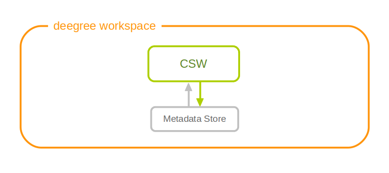
|
Tip
|
In order to fully understand deegree CSW configuration, you will have to learn configuration of other workspace aspects as well. Chapter Metadata stores describes the configuration of metadatastores. |
5.4.1. Minimal example
There is no mandatory element, therefore a minimal CSW configuration example looks like this:
CSW config example 1: Minimal configuration
<?xml version="1.0" encoding="UTF-8"?>
<deegreeCSW configVersion="3.4.0"
  xmlns="http://www.deegree.org/services/csw"
  xmlns:xlink="http://www.w3.org/1999/xlink"
  xmlns:xsi="http://www.w3.org/2001/XMLSchema-instance"
  xsi:schemaLocation="http://www.deegree.org/services/csw
  http://schemas.deegree.org/services/csw/3.4.0/csw_configuration.xsd">
</deegreeCSW>
5.4.2. Configuration overview
The deegree CSW config file format is defined by schema file http://schemas.deegree.org/services/csw/3.4.0/csw_configuration.xsd. The root element is deegreeCSW and the config attribute must be 3.4.0.
The following table lists all available configuration options. When specifiying them, their order must be respected.
| Option | Cardinality | Value | Description |
|---|---|---|---|
SupportedVersions |
0..1 |
String |
Supported CSW Version (Default: 2.0.2) |
MaxMatches |
0..1 |
Integer |
Not negative number of matches (Default:0) |
MetadataStoreId |
0..1 |
String |
Id of the meradatastoreId to use as backenend. By default the only configured store is used. |
EnableTransactions |
0..1 |
Boolean |
Enable transactions (CSW operations) default: disabled. (Default: false) |
EnableInspireExtensions |
0..1 |
Enable the INSPIRE extensions, default: disabled |
|
ExtendedCapabilities |
0..1 |
anyURI |
Include referenced capabilities section. |
ElementNames |
0..1 |
List of configured return profiles. See following xml snippet for detailed informations. |
...
 <ElementNames>
   <!-- Can contain multiuple sets of element names -->
   <ElementName>
     <!-- name of this set. Used <csw:ElementName>Base</csw:ElementName>
          in a reqest to query this profile -->
     <name>Base</name>
     <!-- List of XPath elements to return. If an element node is specified
          the complete node is returned -->
     <XPath>/gmd:MD_Metadata/gmd:language</XPath>
     <XPath>/gmd:MD_Metadata/gmd:fileIdentifier</XPath>
     <XPath>/gmd:MD_Metadata/gmd:hierarchyLevel</XPath>
  </ElementName>
  ...
 <ElementName>
...
5.4.3. Extended Functionality
-
deegree3 CSW supports JSON as additional output format. Use outputFormat="application/json" in your GetRecords or GetRecordById Request to get the matching records in JSON.
5.5. Web Processing Service (WPS)
A deegree WPS allows the invocation of geospatial processes. The offered processes are determined by the attached process provider resources.
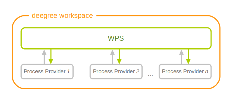
|
Tip
|
In order to fully master deegree WPS configuration, you will have to understand Process providers as well. |
5.5.1. Minimal example
A minimal valid WPS configuration example looks like this:
<deegreeWPS configVersion="3.4.0" xmlns="http://www.deegree.org/services/wps" xmlns:xsi="http://www.w3.org/2001/XMLSchema-instance"
  xsi:schemaLocation="http://www.deegree.org/services/wps http://schemas.deegree.org/services/wps/3.1.0/wps_configuration.xsd">
</deegreeWPS>
This will create a WPS resource with the following properties:
-
All WPS protocol versions are enabled. Currently, this is only 1.0.0.
-
The WPS resource will attach to all process provider resources in the workspace.
-
Temporary files (e.g. for process results) are stored in the standard Java temp directory of the deegree webapp.
-
The last 100 process executions are tracked.
-
Memory buffers (e.g. for inline XML inputs) are limited to 1 MB each. If this limit is exceeded, buffering is switched to use a file in the storage directory.
5.5.2. Complex example
A more complex configuration example looks like this:
<deegreeWPS configVersion="3.4.0" xmlns="http://www.deegree.org/services/wps" xmlns:xsi="http://www.w3.org/2001/XMLSchema-instance"
  xsi:schemaLocation="http://www.deegree.org/services/wps http://schemas.deegree.org/services/wps/3.1.0/wps_configuration.xsd">

  <SupportedVersions>
    <Version>1.0.0</Version>
  </SupportedVersions>

  <DefaultExecutionManager>
    <StorageDir>../var/wps/</StorageDir>
    <TrackedExecutions>1000</TrackedExecutions>
    <InputDiskSwitchLimit>1048576</InputDiskSwitchLimit>
  </DefaultExecutionManager>

</deegreeWPS>
This will create a WPS resource with the following properties:
-
Enabled WPS protocol versions: 1.0.0
-
The WPS resource will attach to all process provider resources in the workspace.
-
Storage directory for temporary files (e.g. for process results) is /var/wps inside the workspace.
-
The last 1000 process executions will be tracked.
-
Memory buffers (e.g. for inline XML inputs) are limited to 1 MB each. If this limit is exceeded, buffering is switched to use a file in the storage directory.
5.5.3. Configuration overview
The deegree WPS config file format is defined by schema file http://schemas.deegree.org/services/wps/3.1.0/wps_configuration.xsd. The root element is deegreeWPS and the config attribute must be 3.1.0. The following table lists all available configuration options (complex ones contain nested options themselves). When specifiying them, their order must be respected.
| Option | Cardinality | Value | Description |
|---|---|---|---|
SupportedVersions |
0..1 |
Complex |
Activated OGC protocol versions, default: all |
DefaultExecutionManager |
0..1 |
Complex |
Settings for tracking process executions |
The remainder of this section describes these options and their sub-options in detail.
-
SupportedVersions: By default, all implemented WMS protocol versions are activated. Currently, this is just 1.0.0 anyway. Alternatively you can control offered WPS protocol versions using the element SupportedVersions. This element allows the child element <Version>1.0.0</Version> for now.
5.5.4. DefaultExecutionManager section
This section controls aspects that are related to temporary storage (for input and output parameter values) during the execution of processes. The DefaultExecutionManager option has the following sub-options:
| Option | Cardinality | Value | Description |
|---|---|---|---|
StorageDir |
0..1 |
String |
Directory for storing execution-related data, default: Java tempdir |
TrackedExecutions |
0..1 |
Integer |
Number of executions to track, default: 100 |
InputDiskSwitchLimit |
0..1 |
Integer |
Limit in bytes, before a ComplexInputInput is written to disk, default: 1 MiB |
5.6. Metadata
This section describes the configuration for the different types of metadata that a service reports in the GetCapabilities response. These options don’t affect the data that the service offers or the behaviour of the service. It merely changes the descriptive metadata that the service reports.
In order to configure the metadata for a web service instance xyz, create a corresponding xyz_metadata.xml file in the services directory of the workspace. The actual service type does not matter, the configuration works for all types of service alike.
Example for deegreeServicesMetadata
<deegreeServicesMetadata xmlns="http://www.deegree.org/services/metadata"
xmlns:xsi="http://www.w3.org/2001/XMLSchema-instance" configVersion="3.4.0"
xsi:schemaLocation="http://www.deegree.org/services/metadata http://schemas.deegree.org/services/metadata/3.4.0/metadata.xsd">
<ServiceIdentification>
<Title>INSPIRE Addresses</Title>
<Abstract>Direct Access Download Service for INSPIRE Addresses</Abstract>
</ServiceIdentification>
<ServiceProvider>
<ProviderName>The deegree project</ProviderName>
<ProviderSite>http://www.deegree.org</ProviderSite>
<ServiceContact>
<IndividualName>Markus Schneider</IndividualName>
<PositionName>deegree TMC</PositionName>
<Phone>0228/18496-0</Phone>
<Facsimile>0228/18496-29</Facsimile>
<ElectronicMailAddress>info@lat-lon.de</ElectronicMailAddress>
<Address>
<DeliveryPoint>Aennchenstr. 19</DeliveryPoint>
<City>Bonn</City>
<AdministrativeArea>NRW</AdministrativeArea>
<PostalCode>53177</PostalCode>
<Country>Germany</Country>
</Address>
<OnlineResource>http://www.deegree.org</OnlineResource>
<HoursOfService>24x7</HoursOfService>
<ContactInstructions>Do not hesitate to call</ContactInstructions>
<Role>PointOfContact</Role>
</ServiceContact>
</ServiceProvider>
<DatasetMetadata>
<MetadataUrlTemplate>http://www.nationaalgeoregister.nl/geonetwork/srv/nl/csw?service=CSW&request=GetRecordById&version=2.0.2&id=${metadataSetId}</MetadataUrlTemplate>
<Dataset>
<Name xmlns:ad="urn:x-inspire:specification:gmlas:Addresses:3.0">ad:Address</Name>
<Title>ad:Address</Title>
<Abstract>Harmonized INSPIRE Addresses (Annex I)</Abstract>
<MetadataSetId>beefcafe-beef-cafe-beef-cafebeefcaf</MetadataSetId>
</Dataset>
</DatasetMetadata>
<ExtendedCapabilities protocolVersions="2.0.0">
<inspire_dls:ExtendedCapabilities xmlns:inspire_dls="http://inspire.ec.europa.eu/schemas/inspire_dls/1.0"
xmlns:inspire_common="http://inspire.ec.europa.eu/schemas/common/1.0"
xsi:schemaLocation="http://inspire.ec.europa.eu/schemas/common/1.0 http://inspire.ec.europa.eu/schemas/common/1.0/common.xsd http://inspire.ec.europa.eu/schemas/inspire_dls/1.0 http://inspire.ec.europa.eu/schemas/inspire_dls/1.0/inspire_dls.xsd">
<inspire_common:MetadataUrl>
<inspire_common:URL>http://www.nationaalgeoregister.nl/geonetwork/srv/nl/csw?service=CSW&request=GetRecordById&version=2.0.2&id=eea97fc0-8291-11e1-afa6-0800200c9a66</inspire_common:URL>
<inspire_common:MediaType>application/vnd.iso.19139+xml</inspire_common:MediaType>
</inspire_common:MetadataUrl>
<inspire_common:SupportedLanguages>
<inspire_common:DefaultLanguage>
<inspire_common:Language>ger</inspire_common:Language>
</inspire_common:DefaultLanguage>
</inspire_common:SupportedLanguages>
<inspire_common:ResponseLanguage>
<inspire_common:Language>ger</inspire_common:Language>
</inspire_common:ResponseLanguage>
<inspire_dls:SpatialDataSetIdentifier>
<inspire_common:Code>eea97fc0-8291-11e1-afa6-0800200c9a66</inspire_common:Code>
</inspire_dls:SpatialDataSetIdentifier>
</inspire_dls:ExtendedCapabilities>
</ExtendedCapabilities>
</deegreeServicesMetadata>The metadata config file format is defined by schema file http://schemas.deegree.org/services/metadata/3.4.0/metadata.xsd. The root element is deegreeServicesMetadata and the config attribute must be 3.4.0. The following table lists all available configuration options (complex ones contain nested options themselves). When specifiying them, their order must be respected.
| Option | Cardinality | Value | Description |
|---|---|---|---|
ServiceIdentification |
1..1 |
Complex |
Metadata that describes the service |
ServiceProvider |
1..1 |
Complex |
Metadata that describes the provider of the service |
DatasetMetadata |
0..1 |
Complex |
Metadata on the datasets provided by the service |
ExtendedCapabilities |
0..n |
Complex |
Extended Metadata reported in OperationsMetadata section |
The remainder of this section describes these options and their sub-options in detail.
|
Warning
|
If a metadata configuration file exists, extended capabilities configured in any service configuration (see chapters Web Feature Service (WFS) and Web Map Service (WMS)) are ignored. Instead, all extended capabilities must be configured in this file. |
5.6.1. Service identification
The ServiceIdentification option has the following sub-options:
| Option | Cardinality | Value | Description |
|---|---|---|---|
Title |
0..n |
String |
Title of the service |
Abstract |
0..n |
String |
Abstract |
Keywords |
0..n |
Complex |
Keywords that describe the service |
Fees |
0..1 |
String |
Fees that apply for using this service |
AccessConstraints |
0..n |
String |
Access constraints for this service |
5.6.2. Service provider
The ServiceProvider option has the following sub-options:
| Option | Cardinality | Value | Description |
|---|---|---|---|
ProviderName |
0..1 |
String |
Name of the service provider |
ProviderSite |
0..1 |
String |
Website of the service provider |
ServiceContact |
0..1 |
Complex |
Contact information |
5.6.3. Dataset metadata
This type of metadata is attached to the datasets that a service offers (e.g. layers for the WMS or feature types for the WFS). The services themselves may have specific mechanisms to override this metadata, so make sure to have a look at the appropriate service sections. However, some metadata configuration can be done right here.
To start with, you’ll need to add a DatasetMetadata container element:
<DatasetMetadata>
...
</DatasetMetadata>
Apart from the descriptive metadata (title, abstract etc.) for each dataset, you can also configure _MetadataURL_s, external metadata links and metadata as well as external metadata IDs.
For general MetadataURL configuration, you can configure the element MetadataUrlTemplate. Its content can be any URL, which may contain the pattern ${metadataSetId}. For each dataset (layer, feature type) the service will output a MetadataURL based on that pattern, if a MetadataSetId has been configured for that dataset (see below). The template is optional, if omitted, no MetadataURL will be produced.
Configuration for the template looks like this:
<DatasetMetadata>
<MetadataUrlTemplate>http://some.url.de/csw?request=GetRecordById&service=CSW&version=2.0.2&outputschema=http://www.isotc211.org/2005/gmd&elementsetname=full&id=${metadataSetId}</MetadataUrlTemplate>
...
</DatasetMetadata>You can also configure ExternalMetadataAuthority elements, which are currently only used by the WMS. You can define multiple authorities, with the authority URL as text content and a unique name attribute. For each dataset you can define an ID for an authority by refering to that name. This will generate an AuthorityURL and Identifier pair in WMS capabilities documents (version 1.3.0 only).
Configuration for an external authority looks like this:
<DatasetMetadata>
  <ExternalMetadataAuthority name="myorg">http://www.myauthority.org/metadataregistry/</ExternalMetadataAuthority>
...
</DatasetMetadata>
Now follows the list of the actual dataset metadata. You can add as many as you need:
<DatasetMetadata>
  <MetadataUrlTemplate>...</MetadataUrlTemplate>
  ...
  <Dataset>
  ...
  </Dataset>
  <Dataset>
  ...
  </Dataset>
  ...
</DatasetMetadata>
For each dataset, you can configure the metadata as outlined in the following table:
| Option | Cardinality | Value | Description |
|---|---|---|---|
Name |
1 |
String/QName |
the layer/feature type name you refer to |
Title |
0..n |
String |
can be multilingual by using the lang attribute |
Abstract |
0..n |
String |
can be multilingual by using the lang attribute |
MetadataSetId |
0..1 |
String |
is used to generate MetadataURL s, see above |
ExternalMetadataSetId |
0..n |
String |
is used to generate AuthorityURL s and Identifier s for WMS, see above. Refer to an authority using the authority attribute. |
5.6.4. Extended capabilities
Extended capabilities are generic metadata sections below the OperationsMetadata element in the GetCapabilities response. They are not defined by the OGC service specifications, but by additional guidance documents, such as the INSPIRE Network Service TGs. deegree treats this section as a generic XML element and includes it in the output. If your service supports multiple protocol versions (e.g. a WFS that supports 1.1.0 and 2.0.0), you may include multiple ExtendedCapabilities elements in the metadata configuration and use attribute protocolVersions to indicate the version that you want to define the extended capabilities for.
5.7. Service controller
The controller configuration is used to configure various global aspects that affect all services.
Since it’s a global configuration file for all services, it’s called main.xml, and located in the services directory. All of the options are optional, and you can also omit the file completely.
An empty example file looks like follows:
<?xml version='1.0'?>
<deegreeServiceController xmlns='http://www.deegree.org/services/controller' configVersion='3.4.0'>
</deegreeServiceController>
The following table lists all available configuration options. When specifiying them, their order must be respected.
| Option | Cardinality | Value | Description |
|---|---|---|---|
ReportedUrls |
0..1 |
Complex |
Hardcode reported URLs in service responses |
PreventClassloaderLeaks |
0..1 |
Boolean |
TODO |
RequestLogging |
0..1 |
Complex |
TODO |
ValidateResponses |
0..1 |
Boolean |
TODO |
RequestTimeoutMilliseconds |
0..n |
Complex |
Maximum request execution time |
The following sections describe the available options in detail.
5.7.1. Reported URLs
Some web service responses contain URLs that refer back to the service, for example in capabilities documents (responses to GetCapabilities requests). By default, deegree derives these URLs from the incoming request, so you don’t have to think about this, even when your server has multiple network interfaces or hostnames. However, sometimes it is required to override these URLs, for example when using deegree behind a proxy or load balancer.
|
Tip
|
If you don’t have a proxy setup that requires it, don’t configure the reported URLs. In standard setups, the default behaviour works best. |
To override the reported URLs, put a fragment like the following into the main.xml:
<ReportedUrls>
  <Services>http://www.mygeoportal.com/ows</Services>
  <Resources>http://www.mygeoportal.com/ows-resources</Resources>
</ReportedUrls>
For this example, deegree would report http://www.mygeoportal.com/ows as service endpoint URL in capabilities responses, regardless of the real connection details of the deegree server. If a specific service is contacted on the deegree server, for example via a request to http://realnameofdeegreemachine:8080/deegree-webservices/services/inspire-wfs-ad, deegree would report http://www.mygeoportal.com/ows/inspire-wfs-ad.
The URL configured by Resources relates to the reported URL of the resources servlet, which allows to access parts of the active deegree workspace via HTTP. Currently, this is only used in WFS DescribeFeatureType responses that access GML application schema directories.
The URLs changed by this configuration option are overwritten by the URL specified by the X-Forwarded-Host, X-Forwarded-Port and X-Forwarded-Proto header values. For example via a request to http://realnameofdeegreemachine:8080/deegree-webservices/services/inspire-wfs-ad and the specified header values
* X-Forwarded-Host = www.mysecondgeoportal.com
* X-Forwarded-Port = 8088
* X-Forwarded-Proto = https
deegree would report https://www.mysecondgeoportal.com:8088/deegree-webservices/services/inspire-wfs-ad. The URL path is kept as in the request URL. Host, port and protocol are replaced by the values from the header. If X-Forwarded-Port or X-Forwarded-Proto are missing the values are taken from the request URL, deegree would report http://www.mysecondgeoportal.com/deegree-webservices/services/inspire-wfs-ad. This behaviour is usefull when the deegree webservice can be requested via different URLs.
5.7.2. Request timeouts
By default, the execution time of a request to a web service is not constrained. It depends on the complexity of the request and the configuration — it’s well possible to create a WMS configuration and a GetMap request that will require hours of processing time. Generally, it is the responsibility of the configuration creator to ensure that service requests will return in a reasonable time (e.g. by applying scale limitations in the layer configuration).
Nevertheless, it is sometimes desirable to enforce an execution time limit. This can be achieved by using the RequestTimeoutMilliseconds option:
...
  <RequestTimeoutMilliseconds serviceId="wms1" request="GetMap">1000</RequestTimeoutMilliseconds>
  <RequestTimeoutMilliseconds serviceId="wms2" request="GetMap">2500</RequestTimeoutMilliseconds>
...
This example enforces the following time-out behaviour:
-
GetMap requests to WMS instance wms1 will be interrupted after an execution time of 1000 milliseconds
-
GetMap requests to WMS instance wms2 will be interrupted after an execution time of 2500 milliseconds
Besides the time-out value in milliseconds, the following sub-options are supported by RequestTimeoutMilliseconds:
| Option | Cardinality | Value | Description |
|---|---|---|---|
@serviceId |
1 |
String |
Resource identifier of the service |
@request |
1 |
String |
Service request |
|
Note
|
A time-out value can be configured for any service type and request. However, a correct termination of requests requires that the relevant Java code is actually interruptible. So far, this has only been verified for GetMap requests to WMS based on feature layers. |
6. Feature stores
Feature stores are workspace resources that provide access to stored features. The two most common use cases for feature stores are:
-
Accessing via Web Feature Service (WFS)
-
Providing of data for Feature layers
The remainder of this chapter describes some relevant terms and the feature store configuration files in detail. You can access this configuration level by clicking feature stores in the service console. The corresponding resource configuration files are located in subdirectory datasources/feature/ of the active deegree workspace directory.
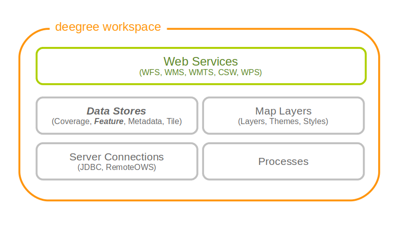
6.1. Features, feature types and application schemas
Features are abstractions of real-world objects, such as rivers, buildings, streets or state boundaries. They are the geo objects of a particular application domain.
A feature types defines the data model for a class of features. For example, a feature type River could define a class of river features that all have the same properties.
6.1.1. Simple vs. rich features and feature types
Some feature types have a more complex structure than others. Traditionally, GIS software copes with "simple" feature types:
-
Every property is either simple (string, number, date, etc.) or a geometry
-
Only a single property with one name is allowed
Basically, a simple feature type is everything that can be represented using a single database table or a single shape file. In contrast, "rich" feature types additionally allow the following:
-
Multiple properties with the same name
-
Properties that contain other features
-
Properties that reference other features or GML objects
-
Properties that contain GML core datatypes which are not geometries (e.g. code types or units of measure)
-
Properties that contain generic XML
Example of a rich feature instance encoded in GML
<ad:Address gml:id="AD_ADDRESS_b15cd863-1b47-4f3c-9cd5-d5283d674a2b">
  <ad:inspireId>
    <base:Identifier xmlns:base="urn:x-inspire:specification:gmlas:BaseTypes:3.2">
      <base:localId>0532200000000003</base:localId>
      <base:namespace>NL.KAD.BAG</base:namespace>
    </base:Identifier>
  </ad:inspireId>
  <ad:position>
    <ad:GeographicPosition>
      <ad:geometry>
        <gml:Point gml:id="POINT_64fae7bf-a836-44af-a63c-349bed1c6f55" srsName="urn:ogc:def:crs:EPSG::4258">
          <gml:pos>52.689618 5.246345</gml:pos>
        </gml:Point>
      </ad:geometry>
      <ad:specification>entrance</ad:specification>
      <ad:method>byOtherParty</ad:method>
      <ad:default>true</ad:default>
    </ad:GeographicPosition>
  </ad:position>
  <ad:locator>
    <ad:AddressLocator>
      <ad:designator>
        <ad:LocatorDesignator>
          <ad:designator>1</ad:designator>
          <ad:type>2</ad:type>
        </ad:LocatorDesignator>
      </ad:designator>
      <ad:level>unitLevel</ad:level>
    </ad:AddressLocator>
  </ad:locator>
  <ad:validFrom>2009-01-05T23:00:00.000</ad:validFrom>
  <ad:validTo>2299-12-30T23:00:00.000</ad:validTo>
  <ad:beginLifespanVersion xsi:nil="true" nilReason="UNKNOWN" />
  <ad:endLifespanVersion xsi:nil="true" nilReason="UNKNOWN" />
  <ad:component xlink:href="#FEATURE_d4a54e57-91cd-410d-9c3d-b0fafdaa080f" />
  <ad:component xlink:href="#FEATURE_240b3dd2-fc1c-448e-82a4-210cffe6dd34" />
  <ad:component xlink:href="#FEATURE_64f481f4-8a21-4474-8efd-28d01db5e2e3" />
</ad:Address>|
Note
|
All deegree feature stores support simple feature types, but only the SQL feature store and the memory feature store support rich feature types. |
6.1.2. Application schemas
An application schema defines a number of feature types for a particular application domain. When referring to an application schema, one usually means a GML application schema that defines a hierarchy of rich feature types. Examples for GML application schemas are:
-
INSPIRE Data Themes (Annex I, II and III)
-
GeoSciML
-
CityGML
-
XPlanung
-
AAA
The following diagram shows a part of the INSPIRE Annex I application schema in UML form:
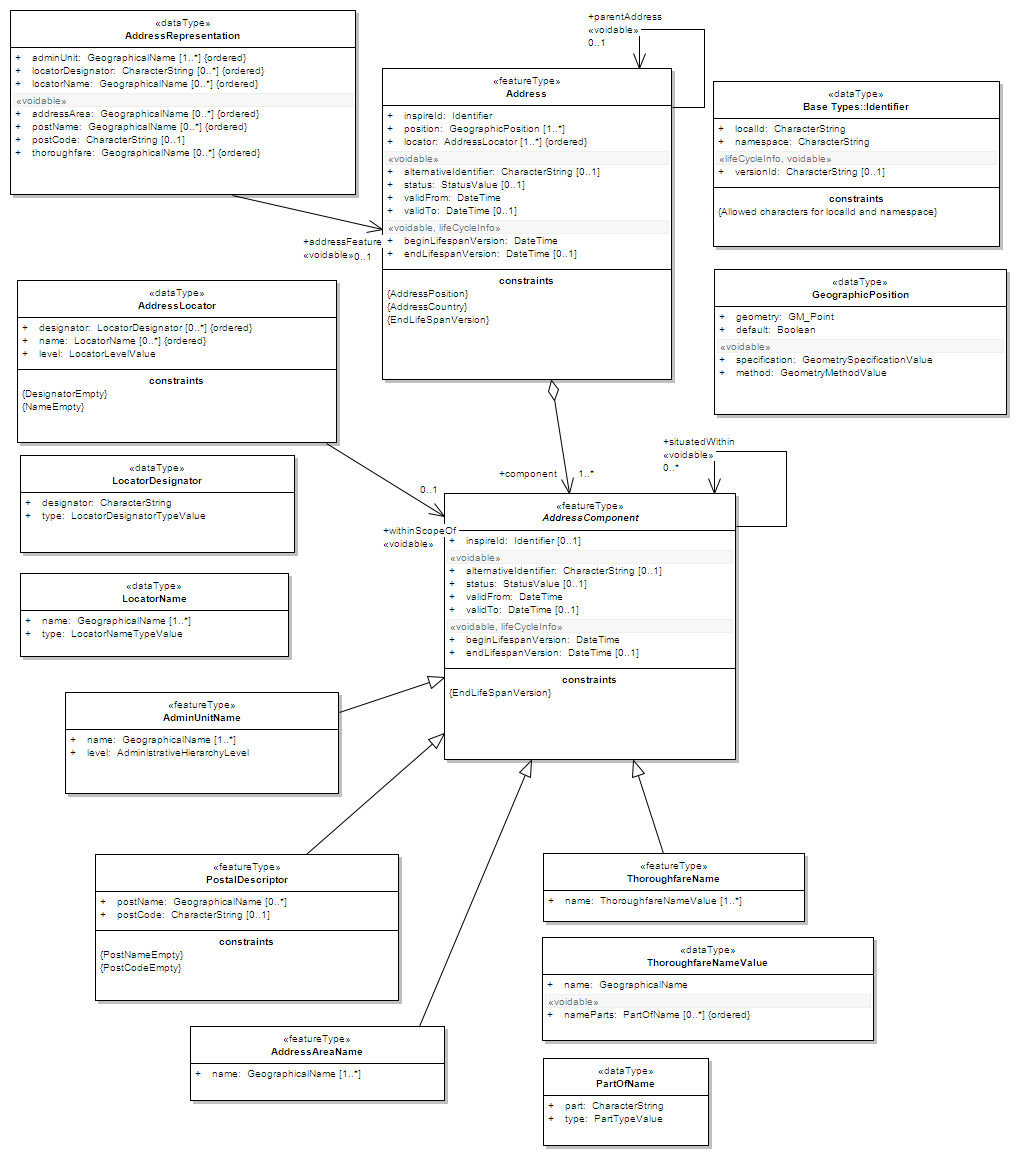
|
Note
|
The SQL feature store or the memory feature store can be used with GML application schemas. |
6.2. Shape feature store
The shape feature store serves a feature type from an ESRI shape file. It is currently not transaction capable and only supports simple feature types.
6.2.1. Minimal configuration example
The only mandatory element is File. A minimal valid configuration example looks like this:
Shape Feature Store config (minimal configuration example)
<ShapeFeatureStore configVersion="3.4.0"
  xmlns="http://www.deegree.org/datasource/feature/shape"
  xmlns:xsi="http://www.w3.org/2001/XMLSchema-instance"
  xsi:schemaLocation="http://www.deegree.org/datasource/feature/shape
  http://schemas.deegree.org/datasource/feature/shape/3.4.0/shape.xsd">

  <!-- Required: Path to shape file on file system (can be relative) -->
  <File>/tmp/rivers.shp</File>

</ShapeFeatureStore>
This configuration will set up a feature store based on the shape file /tmp/rivers.shp with the following settings:
-
The feature store offers the feature type app:rivers (app bound to http://www.deegree.org/app)
-
SRS information is taken from file /tmp/rivers.prj (if it does not exist, EPSG:4326 is assumed)
-
The geometry is added as property app:GEOMETRY
-
All data columns from file /tmp/rivers.dbf are used as properties in the feature type
-
Encoding of text columns in /tmp/rivers.dbf is guessed based on actual contents
-
An alphanumeric index is created for the dbf to speed up filtering based on non-geometric constraints
6.2.2. More complex configuration example
A more complex example that uses all available configuration options:
Shape Feature Store config (more complex configuration example)
<ShapeFeatureStore configVersion="3.4.0"
  xmlns="http://www.deegree.org/datasource/feature/shape"
  xmlns:xsi="http://www.w3.org/2001/XMLSchema-instance"
  xsi:schemaLocation="http://www.deegree.org/datasource/feature/shape
  http://schemas.deegree.org/datasource/feature/shape/3.4.0/shape.xsd">
  <StorageCRS>EPSG:4326</StorageCRS>
  <FeatureTypeName>River</FeatureTypeName>
  <FeatureTypeNamespace>http://www.deegree.org/app</FeatureTypeNamespace>
  <FeatureTypePrefix>app</FeatureTypePrefix>
  <File>/tmp/rivers.shp</File>
  <Encoding>ISO-8859-1</Encoding>
  <GenerateAlphanumericIndexes>false</GenerateAlphanumericIndexes>
  <Mapping>
    <SimpleProperty name="objectid" mapping="OBJECTID" />
    <GeometryProperty name="mygeom" />
  </Mapping>
</ShapeFeatureStore>
This configuration will set up a feature store based on the shape file /tmp/rivers.shp with the following settings:
-
SRS of stored geometries is EPSG:4326 (no auto-detection)
-
The feature store offers the shape file contents as feature type app:River (app bound to http://www.deegree.org/app)
-
Encoding of text columns in /tmp/rivers.dbf is ISO-8859-1 (no auto-detection)
-
No alphanumeric index is created for the dbf (filtering based on non-geometric constraints has to be performed in-memory)
-
The mapping between the shape file columns and the feature type properties is customized.
-
Property objectid corresponds to column OBJECTID of the shape file
-
Property geometry corresponds to the geometry of the shape file
6.2.3. Configuration options
The configuration format for the deegree shape feature store is defined by schema file http://schemas.deegree.org/datasource/feature/shape/3.1.0/shape.xsd. The following table lists all available configuration options. When specifiying them, their order must be respected.
| Option | Cardinality | Value | Description |
|---|---|---|---|
StorageCRS |
0..1 |
String |
CRS of stored geometries |
FeatureTypeName |
0..n |
String |
Local name of the feature type (defaults to base name of shape file) |
FeatureTypeNamespace |
0..1 |
String |
Namespace of the feature type (defaults to "http://www.deegree.org/app") |
FeatureTypePrefix |
0..1 |
String |
Prefix of the feature type (defaults to "app") |
File |
1..1 |
String |
Path to shape file (can be relative) |
Encoding |
0..1 |
String |
Encoding of text fields in dbf file |
GenerateAlphanumericIndexes |
0..1 |
Boolean |
Set to true, if an index for alphanumeric fields should be generated |
Mapping |
0..1 |
Complex |
Customized mapping between dbf column names and property names |
6.3. Memory feature store
The memory feature store serves feature types that are defined by a GML application schema and are stored in memory. It is transaction capable and supports rich GML application schemas.
6.3.1. Minimal configuration example
The only mandatory element is GMLSchema. A minimal valid configuration example looks like this:
Memory Feature Store config (minimal configuration example)
<MemoryFeatureStore configVersion="3.4.0"
  xmlns="http://www.deegree.org/datasource/feature/memory"
  xmlns:xsi="http://www.w3.org/2001/XMLSchema-instance"
  xsi:schemaLocation="http://www.deegree.org/datasource/feature/memory
  http://schemas.deegree.org/datasource/feature/memory/3.4.0/memory.xsd">

  <!-- Required: GML application schema file / directory to read feature types from -->
  <GMLSchema version="GML_32">../../appschemas/inspire/annex1/addresses.xsd</GMLSchema>

</MemoryFeatureStore>
This configuration will set up a memory feature store with the following settings:
-
The GML 3.2 application schema from file ../../appschemas/inspire/annex1/addresses.xsd is used as application schema (i.e. scanned for feature type definitions)
-
No GML datasets are loaded on startup, so the feature store will be empty unless an insertion is performed (e.g. via WFS-T)
6.3.2. More complex configuration example
A more complex example that uses all available configuration options:
Memory Feature Store config (more complex configuration example)
<MemoryFeatureStore configVersion="3.4.0" xmlns="http://www.deegree.org/datasource/feature/memory"
  xmlns:xsi="http://www.w3.org/2001/XMLSchema-instance"
  xsi:schemaLocation="http://www.deegree.org/datasource/feature/memory
  http://schemas.deegree.org/datasource/feature/memory/3.4.0/memory.xsd">
  <StorageCRS>urn:ogc:def:crs:EPSG::4258</StorageCRS>
  <GMLSchema version="GML_32">../../appschemas/inspire/annex1/</GMLSchema>
  <GMLFeatureCollection version="GML_32">../../data/gml/address.gml</GMLFeatureCollection>
  <GMLFeatureCollection version="GML_32">../../data/gml/parcels.gml</GMLFeatureCollection>
</MemoryFeatureStore>
This configuration will set up a memory feature store with the following settings:
-
Directory ../../appschemas/inspire/annex1/ is scanned for *.xsd files. All found files are loaded as a GML 3.2 application schema (i.e. analyzed for feature type definitions).
-
Dataset file ../../data/gml/address.gml is loaded on startup. This must be a GML 3.2 file that contains a feature collection with features that validates against the application schema.
-
Dataset file ../../data/gml/parcels.gml is loaded on startup. This must be a GML 3.2 file that contains a feature collection with features that validates against the application schema.
-
The geometries of loaded features are converted to urn:ogc:def:crs:EPSG::4258.
6.3.3. Configuration options
The configuration format for the deegree memory feature store is defined by schema file http://schemas.deegree.org/datasource/feature/memory/3.0.0/memory.xsd. The following table lists all available configuration options (the complex ones contain nested options themselves). When specifiying them, their order must be respected.
| Option | Cardinality | Value | Description |
|---|---|---|---|
StorageCRS |
0..1 |
String |
CRS of stored geometries |
GMLSchema |
1..n |
String |
Path/URL to GML application schema files/dirs to read feature types from |
GMLFeatureCollection |
0..n |
Complex |
Path/URL to GML feature collections documents to read features from |
6.4. Simple SQL feature store
The simple SQL feature store serves simple feature types that are stored in a spatially-enabled database, such as PostGIS. However, it’s not suited for mapping rich GML application schemas and does not support transactions. If you need these capabilities, use the SQL feature store instead.
|
Tip
|
If you want to use the simple SQL feature store with Oracle or Microsoft SQL Server, you will need to add additional modules first. This is described in Adding database modules. |
6.4.1. Minimal configuration example
There are three mandatory elements: JDBCConnId, SQLStatement and BBoxStatement. A minimal configuration example looks like this:
Simple SQL feature store config (minimal configuration example)
<SimpleSQLFeatureStore configVersion="3.4.0"
xmlns="http://www.deegree.org/datasource/feature/simplesql"
xmlns:xsi="http://www.w3.org/2001/XMLSchema-instance"
xsi:schemaLocation="http://www.deegree.org/datasource/feature/simplesql
http://schemas.deegree.org/datasource/feature/simplesql/3.4.0/simplesql.xsd">
<!-- Required: Database connection -->
<JDBCConnId>connid</JDBCConnId>
<!-- Required: Query statement -->
<SQLStatement>
SELECT name, title, asbinary(the_geom) FROM some_table
WHERE the_geom && st_geomfromtext(?, -1)
</SQLStatement>
<!-- Required: Bounding box statement -->
<BBoxStatement>SELECT astext(ST_Estimated_Extent('some_table', 'the_geom')) as bbox</BBoxStatement>
</SimpleSQLFeatureStore>6.4.2. More complex configuration example
Simple SQL feature store config (more complex configuration example)
<SimpleSQLFeatureStore configVersion="3.4.0"
xmlns="http://www.deegree.org/datasource/feature/simplesql"
xmlns:xsi="http://www.w3.org/2001/XMLSchema-instance"
xsi:schemaLocation="http://www.deegree.org/datasource/feature/simplesql
http://schemas.deegree.org/datasource/feature/simplesql/3.4.0/simplesql.xsd">
<!-- Required: Database connection -->
<JDBCConnId>connid</JDBCConnId>
<!-- Required: Query statement -->
<SQLStatement>
SELECT name, title, asbinary(the_geom) FROM some_table
WHERE the_geom && st_geomfromtext(?, -1)
</SQLStatement>
<!-- Required: Bounding box statement -->
<BBoxStatement>SELECT astext(ST_Estimated_Extent('some_table', 'the_geom')) as bbox</BBoxStatement>
</SimpleSQLFeatureStore>6.4.3. Configuration options
The configuration format is defined by schema file http://schemas.deegree.org/datasource/feature/simplesql/3.0.1/simplesql.xsd. The following table lists all available configuration options (the complex ones contain nested options themselves). When specifiying them, their order must be respected.
| Option | Cardinality | Value | Description |
|---|---|---|---|
StorageCRS |
0..1 |
String |
CRS of stored geometries |
FeatureTypeName |
0..n |
String |
Local name of the feature type (defaults to table name) |
FeatureTypeNamespace |
0..1 |
String |
Namespace of the feature type (defaults to "http://www.deegree.org/app") |
FeatureTypePrefix |
0..1 |
String |
Prefix of the feature type (defaults to "app") |
JDBCConnId |
1..1 |
String |
Identifier of the database connection |
SQLStatement |
1..1 |
String |
SELECT statement that defines the feature type |
BBoxStatement |
1..1 |
String |
SELECT statement for the bounding box of the feature type |
LODStatement |
0..n |
Complex |
Statements for specific WMS scale ranges |
6.5. SQL feature store
The SQL feature store allows to configure highly flexible mappings between feature types and database tables. It can be used for simple mapping tasks (mapping a single database table to a feature type) as well as sophisticated ones (mapping a complete INSPIRE Data Theme to dozens or hundreds of database tables). As an alternative to relational mapping, it additionally offers so-called BLOB mapping which stores any kind of rich feature using a fixed and very simple database schema. In contrast to the simple SQL feature store, the SQL feature store is transaction capable (even for complex mappings) and ideally suited for mapping rich GML application schemas.
6.5.1. Minimal configuration example
A very minimal valid configuration example looks like this:
SQL feature store: Minimal configuration
<SQLFeatureStore configVersion="3.4.0"
  xmlns="http://www.deegree.org/datasource/feature/sql"
  xmlns:xsi="http://www.w3.org/2001/XMLSchema-instance"
  xsi:schemaLocation="http://www.deegree.org/datasource/feature/sql
  http://schemas.deegree.org/datasource/feature/sql/3.4.0/sql.xsd">
  <JDBCConnId>postgis</JDBCConnId>
  <FeatureTypeMapping table="country"/>
</SQLFeatureStore>
This configuration defines a SQL feature store resource with the following properties:
-
JDBC connection resource with identifier postgis is used to connect to the database
-
A single table (country) is mapped
-
Feature type is named app:country (app=http://www.deegree.org/app)
-
Properties of the feature type are automatically derived from table columns
-
Every primitive column (number, string, date) is used as a primitive property
-
Every geometry column is used as a geometry property (storage CRS is determined automatically, inserted geometries are transformed by deegree, if necessary)
-
Feature id (gml:id) is based on primary key column, prefixed by COUNTRY_
-
For insert transactions, it is expected that the database generates new primary keys value automatically (primary key column must have a trigger or a suitable type such as SERIAL in PostgreSQL)
6.5.2. More complex configuration example
A more complex example:
SQL feature store: More complex configuration
<SQLFeatureStore xmlns="http://www.deegree.org/datasource/feature/sql" xmlns:xlink="http://www.w3.org/1999/xlink"
  xmlns:base="urn:x-inspire:specification:gmlas:BaseTypes:3.2" xmlns:ad="urn:x-inspire:specification:gmlas:Addresses:3.0"
  xmlns:gml="http://www.opengis.net/gml/3.2" xmlns:xsi="http://www.w3.org/2001/XMLSchema-instance" configVersion="3.4.0"
  xsi:schemaLocation="http://www.deegree.org/datasource/feature/sql http://schemas.deegree.org/datasource/feature/sql/3.4.0/sql.xsd">
  <JDBCConnId>inspire</JDBCConnId>
  <StorageCRS srid="-1" dim="2D">EPSG:4258</StorageCRS>
  <GMLSchema>../../appschemas/inspire/annex1/Addresses.xsd</GMLSchema>
  <GMLSchema>../../appschemas/inspire/annex1/AdministrativeUnits.xsd</GMLSchema>
  <GMLSchema>../../appschemas/inspire/annex1/CadastralParcels.xsd</GMLSchema>

  <FeatureTypeMapping name="ad:Address" table="ad_address">
    <FIDMapping prefix="AD_ADDRESS_">
      <Column name="attr_gml_id" type="string" />
      <UUIDGenerator />
    </FIDMapping>
    <Complex path="ad:inspireId">
      <Complex path="base:Identifier">
        <Primitive path="base:localId" mapping="localid" />
        <Primitive path="base:namespace" mapping="'NL.KAD.BAG'" />
      </Complex>
    </Complex>
    <Complex path="ad:position">
      <Join table="ad_address_ad_position" fromColumns="fid" toColumns="fk" />
      <Complex path="ad:GeographicPosition">
        <Complex path="ad:geometry">
          <Geometry path="." mapping="value" />
        </Complex>
        <Complex path="ad:specification">
          <Primitive path="text()" mapping="'entrance'" />
        </Complex>
        <Complex path="ad:method">
          <Primitive path="text()" mapping="'byOtherParty'" />
        </Complex>
        <Primitive path="ad:default" mapping="'true'" />
      </Complex>
    </Complex>
    <Complex path="ad:locator">
      <Join table="ad_address_ad_locator" fromColumns="attr_gml_id" toColumns="parentfk" orderColumns="num"
        numbered="true" />
      <Complex path="ad:AddressLocator">
        <Complex path="ad:designator">
          <Join table="ad_address_ad_locator_ad_addresslocator_ad_designator" fromColumns="id" toColumns="parentfk"
            orderColumns="num" numbered="true" />
          <Complex path="ad:LocatorDesignator">
            <Primitive path="ad:designator" mapping="ad_addresslocator_ad_locatordesignator_ad_designator" />
            <Complex path="ad:type">
              <Primitive path="text()" mapping="ad_addresslocator_ad_locatordesignator_ad_type" />
              <Primitive path="@codeSpace" mapping="ad_addresslocator_ad_locatordesignator_ad_type_attr_codespace" />
            </Complex>
          </Complex>
        </Complex>
        <Complex path="ad:level">
          <Primitive path="text()" mapping="ad_addresslocator_ad_level" />
          <Primitive path="@codeSpace" mapping="ad_addresslocator_ad_level_attr_codespace" />
        </Complex>
      </Complex>
    </Complex>
    <Complex path="ad:validFrom">
      <Primitive path="text()" mapping="ad_validfrom" />
      <Primitive path="@nilReason" mapping="ad_validfrom_attr_nilreason" />
      <Primitive path="@xsi:nil" mapping="ad_validfrom_attr_xsi_nil" />
    </Complex>
    <Complex path="ad:validTo">
      <Primitive path="text()" mapping="ad_validto" />
      <Primitive path="@nilReason" mapping="ad_validto_attr_nilreason" />
      <Primitive path="@xsi:nil" mapping="ad_validto_attr_xsi_nil" />
    </Complex>
    <Complex path="ad:beginLifespanVersion">
      <Primitive path="text()" mapping="ad_beginlifespanversion" />
      <Primitive path="@nilReason" mapping="ad_beginlifespanversion_attr_nilreason" />
      <Primitive path="@xsi:nil" mapping="ad_beginlifespanversion_attr_xsi_nil" />
    </Complex>
    <Complex path="ad:endLifespanVersion">
      <Primitive path="text()" mapping="ad_endlifespanversion" />
      <Primitive path="@nilReason" mapping="ad_endlifespanversion_attr_nilreason" />
      <Primitive path="@xsi:nil" mapping="ad_endlifespanversion_attr_xsi_nil" />
    </Complex>
    <Complex path="ad:component">
      <Join table="ad_address_ad_component" fromColumns="attr_gml_id" toColumns="parentfk" orderColumns="num"
        numbered="true" />
      <Feature path=".">
        <Href mapping="href" />
      </Feature>
    </Complex>
  </FeatureTypeMapping>

</SQLFeatureStore>
This configuration snippet defines a SQL feature store resource with the following properties:
-
JDBC connection resource with identifier inspire is used to connect to the database
-
Storage CRS is EPSG:4258, database srid is -1 (inserted geometries are transformed by deegree to the storage CRS, if necessary)
-
Feature types are read from three GML schema files
-
A single feature type ad:Address (ad=urn:x-inspire:specification:gmlas:Addresses:3.0) is mapped
-
The root table of the mapping is ad_address
-
Feature type is mapped to several tables
-
Feature id (gml:id) is based on column attr_gml_id, prefixed by AD_ADDRESS__
-
For insert transactions, new values for column attr_gml_id in the root table are created using the UUID generator. For the joined tables, the database has to create new primary keys value automatically (primary key columns must have a trigger or a suitable type such as SERIAL in PostgreSQL)
6.5.3. Overview of configuration options
The SQL feature store configuration format is defined by schema file http://schemas.deegree.org/datasource/feature/sql/3.4.0/sql.xsd. The following table lists all available configuration options (the complex ones contain nested options themselves). When specifying them, their order must be respected:
| Option | Cardinality | Value | Description |
|---|---|---|---|
<JDBCConnId> |
1 |
String |
Identifier of the database connection |
<DisablePostFiltering> |
0..1 |
Empty |
If present, queries that require in-memory filtering are rejected |
<StorageCRS> |
0..1 |
Complex |
CRS of stored geometries |
<GMLSchema> |
0..n |
String |
Path/URL to GML application schema files/dirs to read feature types from |
<NullEscalation> |
0..1 |
Boolean |
Controls the handling of NULL values on reconstruction from the DB |
<BLOBMapping> |
0..1 |
Complex |
Activates a special mapping mode that uses BLOBs for storing features |
<FeatureTypeMapping> |
0..n |
Complex |
Mapping between a feature type and a database table |
The usage of these options and their sub-options is explained in the remaining sections.
6.5.4. Mapping tables to simple feature types
This section describes how to define the mapping of database tables to simple feature types. Each <FeatureTypeMapping> defines the mapping between one table and one feature type:
SQL feature store: Mapping a single table
<SQLFeatureStore configVersion="3.4.0"
xmlns="http://www.deegree.org/datasource/feature/sql"
xmlns:xsi="http://www.w3.org/2001/XMLSchema-instance"
xsi:schemaLocation="http://www.deegree.org/datasource/feature/sql
  http://schemas.deegree.org/datasource/feature/sql/3.4.0/sql.xsd">
<JDBCConnId>postgis</JDBCConnId>
<FeatureTypeMapping table="country"/>
</SQLFeatureStore>
This example assumes that the database contains a table named country within the default database schema (for PostgreSQL public). Alternatively, you can qualify the table name with the database schema, such as public.country. The feature store will try to automatically determine the columns of the table and derive a suitable feature type:
-
Feature type name: app:country (app=http://www.deegree.org/app)
-
Feature id (gml:id) based on primary key column of table country
-
Every primitive column (number, string, date) is used as a primitive property
-
Every geometry column is used as a geometry property
A single configuration file may map more than one table. The following example defines two feature types, based on tables country and cities.
SQL feature store: Mapping two tables
<SQLFeatureStore configVersion="3.4.0"
  xmlns="http://www.deegree.org/datasource/feature/sql"
  xmlns:xsi="http://www.w3.org/2001/XMLSchema-instance"
  xsi:schemaLocation="http://www.deegree.org/datasource/feature/sql
  http://schemas.deegree.org/datasource/feature/sql/3.4.0/sql.xsd">
  <JDBCConnId>postgis</JDBCConnId>
  <FeatureTypeMapping table="country"/>
  <FeatureTypeMapping table="city"/>
</SQLFeatureStore>
There are several options for <FeatureTypeMapping> that give you more control over the derived feature type definition. The following table lists all available options (the complex ones contain nested options themselves):
| Option | Cardinality | Value | Description |
|---|---|---|---|
table |
1 |
String |
Name of the table to be mapped (can be qualified with database schema) |
name |
0..1 |
QName |
Name of the feature type |
<FIDMapping> |
0..1 |
Complex |
Defines the mapping of the feature id |
<Primitive> |
0..n |
Complex |
Defines the mapping of a primitive-valued column |
<Geometry> |
0..n |
Complex |
Defines the mapping of a geometry-valued column |
|
Note
|
The order of child elements <Primitive> and <Geometry> is not restricted. They may appear in any order. |
These options and their sub-options are explained in the following subsections.
Customizing the feature type name
By default, the name of a mapped feature type will be derived from the table name. If the table is named country, the feature type name will be app:country (app=http://www.deegree.org/app). The name attribute allows to set the feature type name explicity. In the following example, it will be app:Land (Land is German for country).
SQL feature store: Customizing the feature type name
...
  <FeatureTypeMapping table="country" name="Land"/>
...
The name of a feature type is always a qualified XML name. You can use standard XML namespace binding mechanisms to control the namespace and prefix of the feature type name:
SQL feature store: Customizing the feature type namespace and prefix
...
  <FeatureTypeMapping xmlns:myns="http://mydomain.org/myns" table="country" name="myns:Land"/>
...
Customizing the feature id
By default, values for the feature id (gml:id attribute in GML) will be based on the primary key column of the mapped table. Values from this column will be prepended with a prefix that is derived from the feature type name. For example, if the feature type name is app:Country, the prefix is APP_COUNTRY. The feature instance that is built from the table row with primary key 42 will have feature id APP_COUNTRY42.
If this is not what you want, or automatic detection of the primary key column fails, customize the feature id mapping using the <FIDMapping> option:
SQL feature store: Customizing the feature id mapping
...
<FeatureTypeMapping table="country">
  <FIDMapping prefix="C_">
    <Column name="fid" />
  </FIDMapping>
</FeatureTypeMapping>
...
Here are the options for <FIDMapping>:
| Option | Cardinality | Value | Description |
|---|---|---|---|
prefix |
0..1 |
String |
Feature id prefix, default: derived from feature type name |
<Column> |
1..n |
Complex |
Column that stores (a part of) the feature id |
As <Column> may occur more than once, you can define that the feature id is constructed from multiple columns:
SQL feature store: Customizing the feature id mapping
...
<FeatureTypeMapping table="country">
  <FIDMapping prefix="C_">
    <Column name="key1" />
    <Column name="key2" />
  </FIDMapping>
</FeatureTypeMapping>
...
Here are the options for <Column>:
| Option | Cardinality | Value | Description |
|---|---|---|---|
name |
1 |
String |
Name of the database column |
type |
0..1 |
String |
Column type (string, boolean, decimal, double or integer), default: auto |
|
Note
|
Technically, the feature id prefix is important to determine the feature type when performing queries by feature id. Every <FeatureTypeMapping> must have a unique feature id prefix. |
Customizing the mapping between columns and properties
By default, the SQL feature store will try to automatically determine the columns of the table and derive a suitable feature type:
-
Every primitive column (number, string, date) is used as a primitive property
-
Every geometry column is used as a geometry property
If this is not what you want, or automatic detection of the column types fails, use <Primitive> and <Geometry> to control the property definitions of the feature type and the column-to-property mapping:
SQL feature store: Customizing property definitions and the column-to-property mapping
...
  <FeatureTypeMapping table="country">
    <Primitive path="property1" mapping="prop1" type="string"/>
    <Geometry path="property2" mapping="the_geom" type="Point">
      <StorageCRS srid="-1">EPSG:4326</StorageCRS>
    </Geometry>
    <Primitive path="property3" mapping="prop2" type="integer"/>
  </FeatureTypeMapping>
...
This example defines a feature type with three properties:
-
property1, type: primitive (string), mapped to column prop1
-
property2, type: geometry (point), mapped to column the_geom, storage CRS is EPSG:4326, database srid is -1
-
property3, type: primitive (integer), mapped to column prop2
The following table lists all available configuration options for <Primitive> and <Geometry>:
| Option | Cardinality | Value | Description |
|---|---|---|---|
path |
1 |
QName |
Name of the property |
mapping |
1 |
String |
Name of the database column |
type |
1 |
String |
Property/column type |
<Join> |
0..1 |
Complex |
Defines a change in the table context |
<CustomConverter> |
0..1 |
Complex |
Plugs-in a specialized DB-to-ObjectModel converter implementation |
<StorageCRS> |
0..1 |
Complex |
CRS of stored geometries and database srid (only for <Geometry>) |
|
Note
|
If your configuration file is stored in UTF-8 encoding deegree allows special chars from this charset in the mapping (e.g. the property Straße can be stored in the column 'strasse' or 'straße'). Required is that the database supports UTF-8 as well. |
6.5.5. Mapping GML application schemas
The former section assumed a mapping configuration that didn’t use a given GML application schema. If a GML application schema is available and specified using <GMLSchema>, the mapping possibilities and available options are extended. We refer to these two modes as table-driven mode (without GML schema) and schema-driven mode (with GML schema).
Here’s a comparison of table-driven and schema-driven mode:
| Table-driven mode | Schema-driven mode | |
|---|---|---|
GML application schema |
Derived from tables |
Must be provided |
Data model (feature types) |
Derived from tables |
Derived from GML app schema |
GML version |
Any (GML 2, 3.0, 3.1, 3.2) |
Fixed to version of app schema |
Mapping principle |
Property to table column |
XPath-based or BLOB-based |
Supported mapping complexity |
Low |
Very high |
|
Note
|
If you want to create a relational mapping for an existing GML application schema (e.g. INSPIRE Data Themes, GeoSciML, CityGML, XPlanung, AAA), always copy the schema files into the appschemas/ directory of your workspace and reference the schema in your configuration. |
In schema-driven mode, the SQL feature store extracts detailed feature type definitions and property declarations from GML application schema files. A basic configuration for schema-driven mode defines the JDBC connection id, the general CRS of the stored geometries and one or more GML application schema files:
SQL FeatureStore (schema-driven mode): Skeleton config
<SQLFeatureStore configVersion="3.4.0"
  xmlns="http://www.deegree.org/datasource/feature/sql"
  xmlns:xsi="http://www.w3.org/2001/XMLSchema-instance"
  xsi:schemaLocation="http://www.deegree.org/datasource/feature/sql
  http://schemas.deegree.org/datasource/feature/sql/3.4.0/sql.xsd">

  <JDBCConnId>postgis</JDBCConnId>
  <StorageCRS dim="2D" srid="-1">EPSG:4258</StorageCRS>
  <GMLSchema>../../appschemas/inspire/annex1/ad_address.xsd</GMLSchema>

</SQLFeatureStore>
Recommended workflow
|
Note
|
This section assumes that you already have an existing database that you want to map to a GML application schema. If you want to derive a database model from a GML application schema, see Auto-generating a mapping configuration and tables. |
Manually creating a mapping for a rich GML application schema may appear to be a dauting task at first sight. Especially when you are still trying to figure out how the configuration concepts work, you will be using a lot of trial-and-error. Here are some general practices to make this as painless as possible.
-
Map one property of a feature type at a time.
-
Use the Reload link in the services console to activate changes.
-
After changing the configuration file, make sure that the status of the feature store stays green (in the console). If an exclamation mark occurs, you have an error in your configuration. Check the error message and fix it.
-
Check the results of your change (see below)
-
Once you’re satisfied, move on to the next property (or feature type)
Set up a WFS configuration, so you can use WFS GetFeature-requests to check whether your feature mapping works as expected. You can use your web browser for that. After each configuration change, perform a GetFeature-request to see the effect. Suitable WFS requests depend on the WFS version, the GML version and the name of the feature type. Here are some examples:
-
WFS 1.0.0 (GML 2): http://localhost:8080/services?service=WFS&version=1.0.0&request=GetFeature&typeName=ad:Address&maxFeatures=1
-
WFS 1.1.0 (GML 3.1): http://localhost:8080/services?service=WFS&version=1.1.0&request=GetFeature&typeName=ad:Address&maxFeatures=1
-
WFS 2.0.0 (GML 3.2): http://localhost:8080/services?service=WFS&version=2.0.0&request=GetFeature&typeName=ad:Address&count=1
In order to successfully create a mapping for a feature type from a GML application schema, you have to know the structure and the data types of the feature type. For example, if you want to map feature type ad:Address from INSPIRE Annex I, you have to know that it has a required property called ad:inspireId that has a child element with name base:Identifier. Here’s a list of possible options to learn the data model of an application schema:
-
Manually (or with the help of a generic XML tool such as XMLSpy) analyze the GML application schema to determine the feature types and understand their data model
-
Use the services console to auto-generate a mapping configuration (see Auto-generating a mapping configuration and tables). It should reflect the structure and datatypes correctly. Auto-generate the mapping, create a copy of the file and start with a minimal version (FeatureTypeMapping by FeatureTypeMapping, property by property). Adapt it to your own database tables and columns and remove optional elements and attributes that you don’t want to map.
-
Use the deegree support options (mailing lists, commercial support) to get help.
|
Note
|
The deegree project aims for a user-interface to help with all steps of creating mapping configurations. If you are interested in working on this (or funding it), don’t hesitate to contact the project bodies. |
Mapping rich feature types
In schema-driven mode, the <FeatureTypeMapping> element basically works as in table-driven mode (see Mapping tables to simple feature types). It defines a mapping between a table in the database and a feature type. However, there are additional possibilities and it’s usually more suitable to focus on feature types and XML nodes instead of tables and table columns. Here’s an overview of the <FeatureTypeMapping> options and their meaning in schema-driven mode:
| Option | Cardinality | Value | Description |
|---|---|---|---|
table |
1 |
String |
Name of the table to be mapped (can be qualified with database schema) |
name |
0..1 |
QName |
Name of the feature type |
<FIDMapping> |
1 |
Complex |
Defines the mapping of the feature id |
<Primitive> |
0..n |
Complex |
Defines the mapping of a primitive-valued node |
<Geometry> |
0..n |
Complex |
Defines the mapping of a geometry-valued node |
<Complex> |
0..n |
Complex |
Defines the mapping of a complex-valued node |
<Feature> |
0..n |
Complex |
Defines the mapping of a feature-valued node |
|
Note
|
The order of child elements <Primitive>, <Geometry>, <Complex> and <Feature> is not restricted. They may appear in any order. |
We’re going to explore the additional options by describing the necessary steps for mapping feature type ad:Address (from INSPIRE Annex I) to an example database. Start with a single <FeatureTypeMapping>. Provide the table name and the mapping for the feature identifier. The example uses a table named ad_address and a key column named fid:
SQL feature store (schema-driven mode): Start configuration
...
<FeatureTypeMapping name="ad:Address" table="ad_address" xmlns:ad="urn:x-inspire:specification:gmlas:Addresses:3.0">
  <FIDMapping>
    <Column name="fid" />
  </FIDMapping>
</FeatureTypeMapping>
...|
Tip
|
In schema-driven mode, there is no automatic detection of columns, column types or primary keys. You always have to specify <FIDMapping>. |
|
Tip
|
If this configuration matches your database and you have a working WFS resource, you should be able to query the feature type (although no properties will be returned): http://localhost:8080/services?service=WFS&version=2.0.0&request=GetFeature&typeName=ad:Address&count=1 |
Mapping rich feature types works by associating XML nodes of a feature instance with rows and columns in the database. The table context (the current row) is changed when necessary. In the beginning of a <FeatureTypeMapping>, the current context node is an ad:Address element and the current table context is a row of table ad_address. The first (required) property that we’re going to map is ad:inspireId. The schema defines that ad:inspireId has as child element named base:Identifier which in turn has two child elements named base:localId and base:namespace. Lets’s assume that we have a column localid in our table, that we want to map to base:localId, but for base:namespace, we don’t have a corresponding column. We want this element to have the fixed value NL.KAD.BAG for all instances of ad:Address. Here’s how to do it:
SQL feature store (schema-driven mode): Complex elements and constant mappings
<FeatureTypeMapping name="ad:Address" table="ad_address" xmlns:base="urn:x-inspire:specification:gmlas:BaseTypes:3.2" xmlns:ad="urn:x-inspire:specification:gmlas:Addresses:3.0">
  <FIDMapping>
    <Column name="fid" />
  </FIDMapping>

  <Complex path="ad:inspireId">
    <Complex path="base:Identifier">
      <Primitive path="base:localId" mapping="localid"/>
      <Primitive path="base:namespace" mapping="'NL.KAD.BAG'"/>
    </Complex>
  </Complex>

</FeatureTypeMapping>
There are several things to observe here. The Complex element occurs twice. In the path attribute of the first occurrence, we specified the qualified name of the (complex) property we want to map (ad:inspireId). The nested Complex targets child element base:Identifier of ad:inspireId. And finally, the Primitive elements specify that child element base:localId is mapped to column localid and element base:namespace is mapped to constant NL.KAD.BAG (note the single quotes around NL.KAD.BAG).
To summarize:
-
Complex is used to select a (complex) child element to be mapped. It is a container for child mapping elements (Primitive, Geometry, Complex or Feature)
-
In the mapping attribute of Primitive, you can also use constants, not only column names
The next property we want to map is ad:position. It contains the geometry of the address, but the actual GML geometry is nested on a deeper level and the property can occur multiple times. In our database, we have a table named ad_address_ad_position with columns fk (foreign key to ad_address) and value (geometry). Here’s the extended mapping:
SQL feature store (schema-driven mode): Join elements and XPath expressions
<FeatureTypeMapping name="ad:Address" table="ad_address" xmlns:base="urn:x-inspire:specification:gmlas:BaseTypes:3.2" xmlns:ad="urn:x-inspire:specification:gmlas:Addresses:3.0">
  <FIDMapping>
    <Column name="fid" />
  </FIDMapping>

  <Complex path="ad:inspireId">https://xxx[]
    <Complex path="base:Identifier">
      <Primitive path="base:localId" mapping="localid" />
      <Primitive path="base:namespace" mapping="'NL.KAD.BAG'" />
    </Complex>
  </Complex>

  <Complex path="ad:position">
    <Join table="ad_address_ad_position" fromColumns="fid" toColumns="fk" />
    <Complex path="ad:GeographicPosition">
      <Complex path="ad:geometry">
        <Geometry path="." mapping="value" />
      </Complex>
      <Complex path="ad:specification">
        <Primitive path="text()" mapping="'entrance'" />
      </Complex>
      <Complex path="ad:method">
        <Primitive path="text()" mapping="'byOtherParty'" />
      </Complex>
      <Primitive path="ad:default" mapping="'true'" />
    </Complex>
  </Complex>

</FeatureTypeMapping>
Again, the Complex element is used to drill into the XML structure of the property and several elements are mapped to constant values. But there are also new things to observe:
-
The first child element of a <Complex> (or <Primitive>, <Geometry> or <Feature>) can be <Join>. <Join> performs a table change: table rows corresponding to ad:position are not stored in the root feature type table (ad_address), but in a joined table. All siblings of <Join> (or their children) refer to this joined table (ad_address_ad_position). The join condition that determines the related rows in the joined table is ad_address.fid=ad_address_ad_position.fk. <Join> is described in detail in the next section.
-
Valid expressions for path can also be . (current node) and text() (primitive value of the current node).
Let’s move on to the mapping of property ad:component. This property can occur multiple times and contains (a reference to) another feature.
SQL feature store (schema-driven mode): Feature elements
<FeatureTypeMapping name="ad:Address" table="ad_address" xmlns:base="urn:x-inspire:specification:gmlas:BaseTypes:3.2" xmlns:ad="urn:x-inspire:specification:gmlas:Addresses:3.0">
    [...]
    <Complex path="ad:component">
      <Join table="ad_address_ad_component" fromColumns="fid" toColumns="fk"/>
      <Feature path=".">
        <Href mapping="href"/>
      </Feature>
    </Complex>
</FeatureTypeMapping>
As in the mapping of ad:position, a <Join> is used to change the table context. The table that stores the information for ad:component properties is ad_address_ad_component. The <Feature> declares that we want to map a feature-valued node and it’s <Href> sub-element defines that column href stores the value of the xlink:href attribute.
Here is an overview of all options for <Complex> elements:
| Option | Cardinality | Value | Description |
|---|---|---|---|
path |
1 |
QName |
Name/XPath-expression that determines the element to be mapped |
<Join> |
0..1 |
Complex |
Defines a change in the table context |
<CustomConverter> |
0..1 |
Complex |
Plugs-in a specialized DB-to-ObjectModel converter implementation |
<Primitive> |
0..n |
Complex |
Defines the mapping of a primitive-valued node |
<Geometry> |
0..n |
Complex |
Defines the mapping of a geometry-valued node |
<Complex> |
0..n |
Complex |
Defines the mapping of a complex-valued node |
<Feature> |
0..n |
Complex |
Defines the mapping of a feature-valued node |
|
Note
|
The order of child elements <Primitive>, <Geometry>, <Complex> and <Feature> is not restricted. They may appear in any order. |
Here is an overview on all options for <Feature> elements:
| Option | Cardinality | Value | Description |
|---|---|---|---|
path |
1 |
QName |
Name/XPath-expression that determines the element to be mapped |
<CustomConverter> |
0..1 |
Complex |
Plugs-in a specialized DB-to-ObjectModel converter implementation |
<Href> |
0..1 |
Complex |
Defines the column that stores the value for xlink:href |
Mapping strategies for xlink:href attributes
There are two different use cases when xlink:href attributes are used:
-
-
Reference on other feature.
-
-
-
xlink:href value is used as static value. For example, if a user wants to filter on INSPIRE codelists, filtering is executed on the value of xlink:href.
-
Case 1. does not allow filtering on the value of xlink:href itself. Case 2. allows filtering on the static value of the xlink:href attribute but the linked feature is not resolved anymore.
Those two cases can be realized by different mappings in SQL feature store configuration:
-
-
Feature mapping is used:
-
<Feature path=".">
  <Join table="?" fromColumns="designationtype_designation_fk" toColumns="id"/>
  <Href mapping="designationtype_designation_href"/>
</Feature>-
-
Primitive mapping is used:
-
<Primitive path="@xlink:href" mapping="designationtype_designation_href"/>For more details see chapter Mapping rich feature types.
Changing the table context
At the beginning of a <FeatureTypeMapping>, the current table context is the one specified by the table attribute. In the following example snippet, this would be table ad_address.
SQL feature store: Initial table context
<FeatureTypeMapping name="ad:Address" table="ad_address">
 [...]
  <Complex path="gml:identifier">
    <Primitive path="text()" mapping="gml_identifier"/>
    <Primitive path="@codeSpace" mapping="gml_identifier_attr_codespace"/>
  </Complex>
 [...]
</FeatureTypeMapping>
Note that all mapped columns stem from table ad_address. This is fine, as each feature can only have a single gml:identifier property. However, when mapping a property that may occur any number of times, we will have to access the values for this property in a separate table.
SQL feature store: Changing the table context
<FeatureTypeMapping name="ad:Address" table="ad_address">
 [...]
  <Complex path="gml:identifier">
    <Primitive path="text()" mapping="gml_identifier"/>
    <Primitive path="@codeSpace" mapping="gml_identifier_attr_codespace"/>
  </Complex>
 [...]
  <Complex path="ad:position">
    <Join table="ad_address_ad_position" fromColumns="attr_gml_id" toColumns="parentfk" orderColumns="num" numbered="true"/>
    <Complex path="ad:GeographicPosition">
     <Complex path="ad:geometry">
       <Primitive path="@nilReason" mapping="ad_geographicposition_ad_geometry_attr_nilreason"/>
       <Primitive path="@gml:remoteSchema" mapping="ad_geographicposition_ad_geometry_attr_gml_remoteschema"/>
       <Primitive path="@owns" mapping="ad_geographicposition_ad_geometry_attr_owns"/>
       <Geometry path="." mapping="ad_geographicposition_ad_geometry_value"/>
     </Complex>
     [...]
     <Primitive path="ad:default" mapping="ad_geographicposition_ad_default"/>
   </Complex>
 </Complex>
 [...]
</FeatureTypeMapping>
In this example, property gml:identifier is mapped as before (the data values stem from table ad_address). In contrast to that, property ad:position can occur any number of times for a single ad_address feature instance. In order to reflect that in the relational model, the values for this property have to be taken from/stored in a separate table. The feature type table (ad_address) must have a 1:n relation to this table.
The <Join> element is used to define such a change in the table context (in other words: a relation/join between two tables). A <Join> element may only occur as first child element of any of the mapping elements (<Primitive>, <Geometry>, <Feature> or <Complex>). It changes from the current table context to another one. In the example, the table context in the mapping of property ad:position is changed from ad_address to ad_address_ad_position. All mapping instructions that follow the <Join> element refer to the new table context. For example, the geometry value is taken from ad_address_ad_position.ad_geographicposition_ad_geometry_value.
The following table lists all available options for <Join> elements:
| Option | Cardinality | Value | Description |
|---|---|---|---|
table |
1..1 |
String |
Name of the target table to change to. |
fromColumns |
1..1 |
String |
One or more columns that define the join key in the source table. |
toColumns |
1..1 |
String |
One or more columns that define the join key in the target table. |
orderColumns |
0..1 |
String |
One or more columns hat define the order of the joined rows. |
numbered |
0..1 |
Boolean |
Set to true, if orderColumns refers to a single column that contains natural numbers [1,2,3,…]. |
<AutoKeyColumn> |
0..n |
Complex |
Columns in the target table that store autogenerated keys (only required for transactions). |
Attributes fromColumns, toColumns and orderColumns may each contain one or more columns. When specifying multiple columns, they must be given as a whitespace-separated list. orderColumns is used to force a specific ordering on the joined table rows. If this attribute is omitted, the order of joined rows is not defined and reconstructed feature instances may vary each time they are fetched from the database. In the above example, this would mean that the multiple ad:position properties of an ad:Address feature may change their order.
In case that the order column stores the child index of the XML element, the numbered attribute should be set to true. In this special case, filtering on property names with child indexes will be correctly mapped to SQL WHERE clauses as in the following WFS example request.
SQL feature store: WFS query with child index
<GetFeature version="2.0.0" service="WFS">
  <Query typeNames="ad:Address">
    <fes:Filter>
      <fes:BBOX>
        <fes:ValueReference>ad:position[3]/ad:GeographicPosition/ad:geometry</fes:ValueReference>
        <gml:Envelope srsName="urn:ogc:def:crs:EPSG::4258">
          <gml:lowerCorner>52.691 5.244</gml:lowerCorner>
          <gml:upperCorner>52.711 5.245</gml:upperCorner>
        </gml:Envelope>
      </fes:BBOX>
    </fes:Filter>
  </Query>
</GetFeature>
In the above example, only those ad:Address features will be returned where the geometry in the third ad:position property has an intersection with the specified bounding box. If only other ad:position properties (e.g. the first one) matches this constraint, they will not be included in the output.
The <AutoKeyColumn> configuration option is only required when you want to use transactions on your feature store and your relational model is non-canonical. Ideally, the mapping will only change the table context in case the feature type model allows for multiple child elements at that point. In other words: if the XML schema has maxOccurs set to unbounded for an element, the relational model should have a corresponding 1:n relation. For a 1:n relation, the target table of the context change should have a foreign key column that points to the primary key column of the source table of the context change. This is important, as the SQL feature store has to propagate keys from the source table to the target table and store them there as well.
If the joined table is the origin of other joins, than it is important that the SQL feature store can generate primary keys for the join table. If not configured otherwise, it is assumed that column id stores the primary key and that the database will auto-generate values on insert using database mechanisms such as sequences or triggers.
If this is not the case, use the AutoKeyColumn options to define the columns that make up the primary key in the join table and how the values for these columns should be generated on insert. Here’s an example:
SQL feature store: Key propagation for transactions
[...]
<Join table="B" fromColumns="id" toColumns="parentfk" orderColumns="num" numbered="true">
  <AutoKeyColumn name="pk1">
    <UUIDGenerator />
  </AutoKeyColumn>
  [...]
  <Join table="C" fromColumns="pk1" toColumns="parentfk" />
  [...]
</Join>
[...]
In this example snippet, the primary key for table B is stored in column pk1 and values for this column are generated using the UUID generator. There’s another change in the table context from B to C. Rows in table C have a key stored in column parentfk that corresponds to the B.pk1. On insert, values generated for B.pk1 will be propagated and stored for new rows in this table as well. The following table lists the options for <AutoKeyColumn> elements.
Inside a <AutoKeyColumn>, you may use the same key generators that are available for feature id generation (see above).
Handling of NULL values
By default, a NULL value in a mapped database column means that just the mapped particle is omitted from the reconstructed feature. However, if the corresponding element/attribute or text node is required according to the GML application schema, this will lead to invalid feature instances. In order to deal with this, the global option <NullEscalation> should be set to true after the mapping configuration has been finished.
SQL feature store: Activating NULL value escalation
[...]
<NullEscalation>true</NullEscalation>
[...]
If this option is turned on and a NULL value is found in a mapped column, the following strategy is applied:
-
If the corresponding particle is not required according to the GML application schema, just this particle is omitted.
-
If the container element of the particle is nillable according to the GML application schema, the xsi:nil attribute of the element is set to true.
-
In all other cases, the NULL is escalated to the container element using the same strategy (until the feature level has been reached).
This works well most of the times, but sometimes, it can be handy to override this behaviour. For that, each <Primitive>, <Complex>, <Geometry> or <Feature> configuration element supports the optional attribute nullEscalation. The following config snippet demonstrates a custom NULL escalation for element gml:endPosition. By default, the content of this element is required, but by setting it to false, NULL escalation can be manually switched off for this very particle.
SQL feature store: Customizing NULL value escalation
[...]
<Complex path="gml:TimePeriod">
  <Complex path="gml:beginPosition">
    <Primitive path="text()" mapping="begin_position"/>
  </Complex>
  <Complex path="gml:endPosition">
    <Primitive path="@indeterminatePosition" mapping="end_position_indeterminate_position"/>
    <Primitive path="text()" mapping="end_position" nullEscalation="false"/>
  </Complex>
</Complex>
[...]
The following values are supported for attribute nullEscalation on <Primitive>, <Complex>, <Geometry> or <Feature> elements:
-
auto: Handling of NULL values is derived from the GML application schema. Same as omitting the nullEscalation attribute.
-
true: NULL values are escalated to the container element.
-
false: NULL values are not escalated to the container element.
BLOB mapping
An alternative approach to mapping each feature type from an application schema using <FeatureTypeMapping> is to specify a single <BLOBMapping> element. This activates a different storage strategy based on a fixed database schema. Central to this schema is a table that stores every feature instance (and all of it’s properties) as a BLOB (binary large object).
Here is an overview on all options for <BLOBMapping> elements:
| Option | Cardinality | Value | Description |
|---|---|---|---|
<BlobTable> |
0..1 |
String |
Database table that stores features, default: gml_objects |
<FeatureTypeTable> |
0..1 |
String |
Database table that stores feature types, default: feature_types |
The central table (controlled by <BlobTable>) uses the following columns:
| Column | PostGIS type | Used for |
|---|---|---|
id |
serial |
Primary key |
gml_id |
text |
Feature identifier (used for id queries and resolving xlink references) |
gml_bounded_by |
geometry |
Bounding box (used for spatial queries) |
ft_type |
smallint |
Feature type identifier (used to narrow the result set) |
binary_object |
bytea |
Encoded feature instance |
The other table (controlled by <FeatureTypeTable>) stores a mapping of feature type names to feature type identifiers:
| Column | PostGIS type | Used for |
|---|---|---|
id |
smallint |
Primary key |
qname |
text |
Name of the feature type |
bbox |
geometry |
Aggregated bounding box for all features of this type |
|
Note
|
In order for <BLOBMapping> to work, you need to have the correct tables in your database and initialize the feature type table with the names of all feature types you want to use. We recommend not to do this manually, see Auto-generating a mapping configuration and tables. The wizard will also create suitable indexes to speed up queries. |
|
Note
|
You may wonder how to get data into the database in BLOB mode. As for standard mapping, you can do this by executing WFS-T requests or by using the feature store loader. Its usage is described in the last steps of Auto-generating a mapping configuration and tables. |
|
Note
|
In BLOB mode, only spatial and feature id queries can be mapped to SQL WHERE-constraints. All other kinds of filter conditions are performed in memory. See Evaluation of query filters for more information. |
6.5.6. Transactions and feature id generation
The mapping defined by a <FeatureTypeMapping> element generally works in both directions:
-
Table-to-feature-type (query): Feature instances are created from table rows
-
Feature-type-to-table (insert): New table rows are created for inserted feature instances
However, there’s a caveat for inserts: The SQL feature store has to know how to obtain new and unique feature ids.
When features are inserted into a SQL feature store (for example via a WFS transaction), the client can choose between different id generation modes. These modes control whether feature ids (the values in the gml:id attribute) have to be re-generated. There are three id generation modes available, which directly relate to the WFS 1.1.0 specification:
-
UseExisting: The feature store will use the original gml:id values that have been provided in the input. This may lead to errors if the provided ids are already in use or if the format of the id does not match the configuration.
-
GenerateNew: The feature store will discard the original gml:id values and use the configured generator to produce new and unique identifiers. References in the input (xlink:href) that point to a feature with an reassigned id are fixed as well, so reference consistency is ensured.
-
ReplaceDuplicate: The feature store will try to use the original gml:id values that have been provided in the input. If a certain identifier already exists in the database, the configured generator is used to produce a new and unique identifier. NOTE: Support for this mode is not implemented yet.
|
Note
|
In a WFS 1.1.0 insert request, the id generation mode is controlled by attribute idGenMode. WFS 1.0.0 and WFS 2.0.0 don’t support to specify it on a request basis. However, in the deegree WFS configuration you can control it in the option EnableTransactions. |
In order to generate the required ids for GenerateNew, you can choose between different generators. These are configured in the <FIDMapping> child element of <FeatureTypeMapping>:
Auto id generator
The auto id generator depends on the database to provide new values for the feature id column(s) on insert. This requires that the used feature id columns are configured appropriately in the database (e.g. that they have a trigger or a suitable column type such as SERIAL in PostgreSQL).
SQL feature store: Auto id generator example
[...]
<FIDMapping prefix="AD_ADDRESS_">
  <Column name="attr_gml_id" />
  <AutoIDGenerator />
</FIDMapping>
[...]
This snippet defines the feature id mapping and the id generation behaviour for a feature type called ad:Address
-
When querying, the prefix AD_ADDRESS_ is prepended to column attr_gml_id to create the exported feature id. If attr_gml_id contains the value 42 in the database, the feature instance that is created from this row will have the value AD_ADDRESS_42.
-
On insert (mode=UseExisting), provided gml:id values must have the format AD_ADDRESS$. The prefix _AD_ADDRESS_ is removed and the remaining part of the identifier is stored in column attr_gml_id.
-
On insert (mode=GenerateNew), the database must automatically create a new value for column attr_gml_id which will be the postfix of the newly assigned feature id.
UUID generator
The UUID generator generator uses Java’s UUID implementation to generate new and unique identifiers. This requires that the database column for the id is a character column that can store strings with a length of 36 characters and that the database does not perform any kind of insertion value generation for this column (e.g triggers).
SQL feature store: UUID generator example
[...]
<FIDMapping prefix="AD_ADDRESS_">
  <Column name="attr_gml_id" />
  <UUIDGenerator />
</FIDMapping>
[...]
This snippet defines the feature id mapping and the id generation behaviour for a feature type called ad:Address
-
When querying, the prefix AD_ADDRESS_ is prepended to column attr_gml_id to create the exported feature id. If attr_gml_id contains the value 550e8400-e29b-11d4-a716-446655440000 in the database, the feature instance that is created from this row will have the value AD_ADDRESS_550e8400-e29b-11d4-a716-446655440000.
-
On insert (mode=UseExisting), provided gml:id values must have the format AD_ADDRESS$. The prefix _AD_ADDRESS_ is removed and the remaining part of the identifier is stored in column attr_gml_id.
-
On insert (mode=GenerateNew), a new UUID is generated and stored in column attr_gml_id.
Sequence id generator
The sequence id generator queries a database sequence to generate new and unique identifiers. This requires that the database column for the id is compatible with the values generated by the sequence and that the database does not perform any kind of automatical value insertion for this column (e.g triggers).
SQL feature store: Database sequence generator example
[...]
<FIDMapping prefix="AD_ADDRESS_">
  <Column name="attr_gml_id" />
  <SequenceIDGenerator sequence="SEQ_FID">
</FIDMapping>
[...]
This snippet defines the feature id mapping and the id generation behaviour for a feature type called ad:Address
-
When querying, the prefix AD_ADDRESS_ is prepended to column attr_gml_id to create the exported feature id. If attr_gml_id contains the value 42 in the database, the feature instance that is created from this row will have the value AD_ADDRESS_42.
-
On insert (mode=UseExisting), provided gml:id values must have the format AD_ADDRESS$. The prefix _AD_ADDRESS_ is removed and the remaining part of the identifier is stored in column attr_gml_id.
-
On insert (mode=GenerateNew), the database sequence SEQ_FID is queried for new values to be stored in column attr_gml_id.
6.5.7. Evaluation of query filters
The SQL feature store always tries to map filter conditions (e.g. from WFS GetFeature requests or when accessed by the WMS) to SQL-WHERE conditions. However, this is not possible in all cases. Sometimes a filter uses an expression that does not have an equivalent SQL-WHERE clause. For example when using BLOB mapping and the filter is not based on a feature id or a spatial constraint.
In such cases, the SQL feature store falls back to in-memory filtering. It will reconstruct feature by feature from the database and evaluate the filter in memory. If the filter matches, it will be included in the result feature stream. If not, it is skipped.
The downside of this strategy is that it can put a serious load on your server. If you want to turn off in-memory filtering completely, use <DisablePostFiltering>. If this option is specified and a filter requires in-memory filtering, the query will be rejected.
6.5.8. Auto-generating a mapping configuration and tables
Although this functionality is still in beta stage, the services console can be used to automatically derive an SQL feature store configuration and set up tables from an existing GML application schema. If you don’t have an existing database structure that you want to use, you can use this option to create a working database set up very quickly. And even if you have an existing database you need to map manually, this functionality can be prove very helpful to generate a valid mapping configuration to start with.
|
Note
|
As every (optional) attribute and element will be considered in the mapping, you may easily end up with hundreds of tables or columns. |
This walkthrough is based on the INSPIRE Annex I schemas, but you should be able to use these instructions with other GML application schemas as well. Make sure that the INSPIRE workspace has been downloaded and activated as described in Example workspace 1: INSPIRE Network Services. As another prerequisite, you will have to create an empty, spatially-enabled PostGIS database that you can connect to from your deegree installation.
|
Tip
|
Instead of PostGIS, you can also use an Oracle Spatial or an Microsoft SQL Server database. In order to enable support for these databases, see Adding database modules. |
|
Note
|
If the application schema contains UTF-8 characters which are not part of the 7-bit ASCII subset they are normalised during the generation of the feature store configuration for the database mapping (but kept for the feature type names). So the mapping to table and column names contains only 7-bit ASCII character and it is no requirement to the database to use UTF-8. |
As a first step, create a JDBC connection to your database. Click server connections → jdbc and enter inspire (or an other identifier) as connection id:
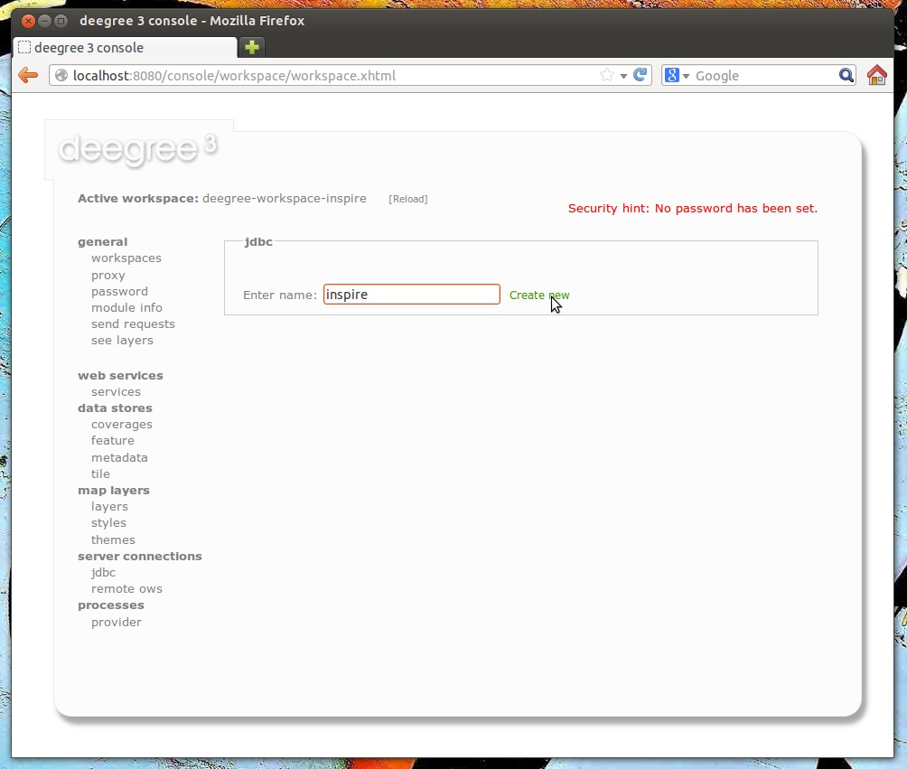
Afterwards, click Create new and enter the connection details to your database:
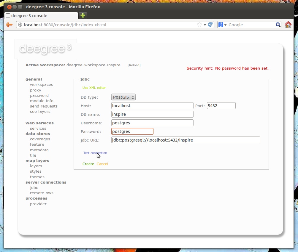
By clicking Test connection, you can ensure that deegree can connect to your database:
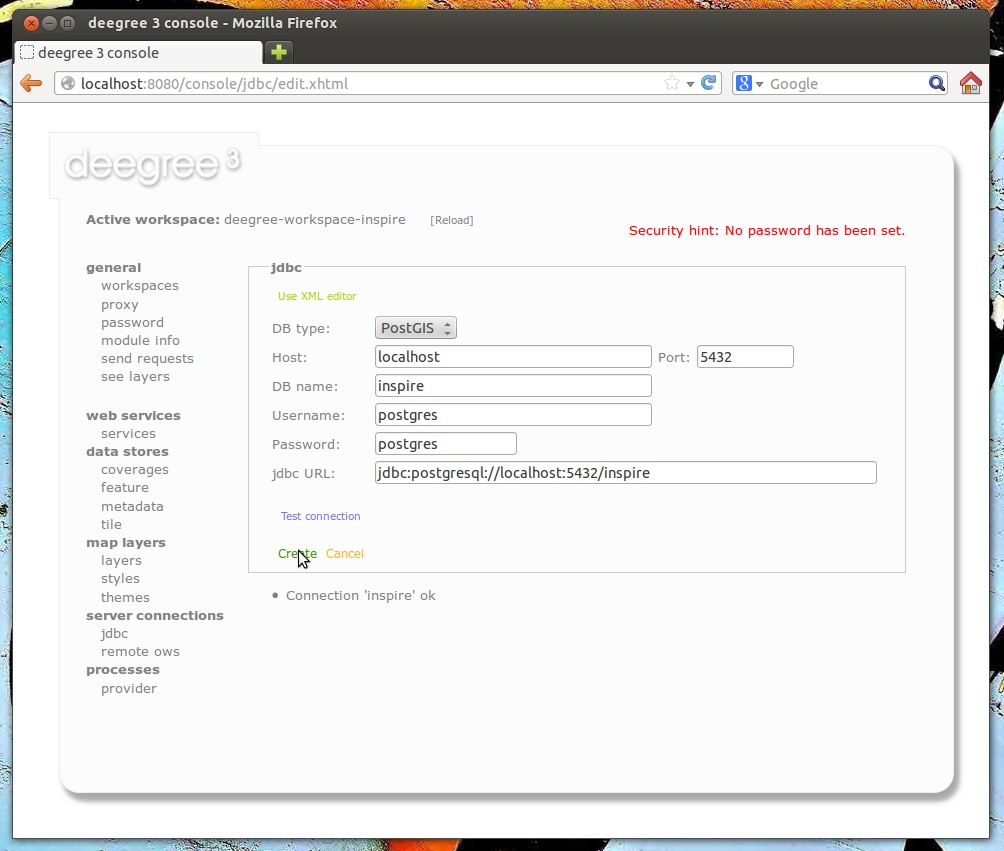
If everything works, click Create to finish the creation of your JDBC resource:
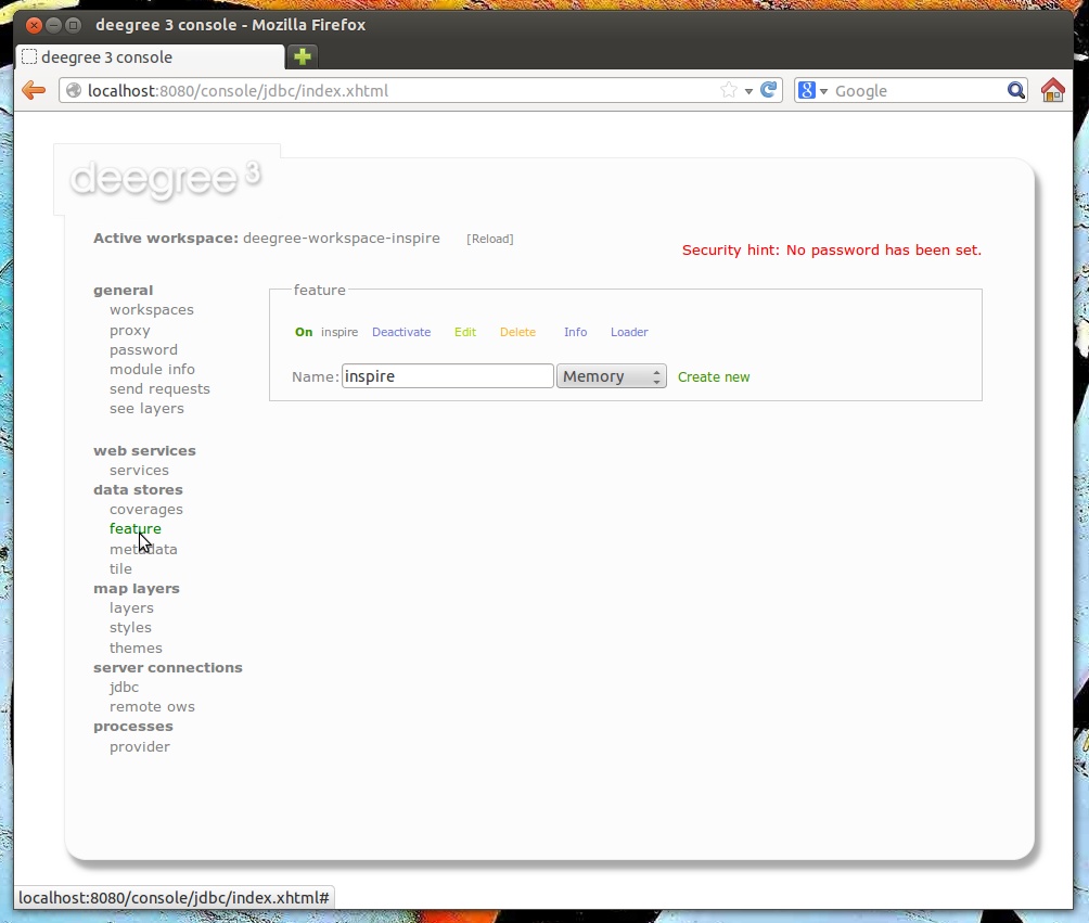
Now, change to data stores → feature. We will have to delete the existing (memory-based) feature store first. Click Delete:

Enter "inspire" as name for the new feature store, select "SQL" from the drop-down box and click Create new:
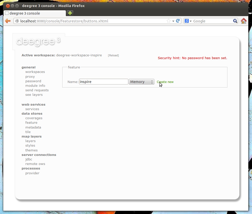
Select "Create tables from GML application schema" and click Next:
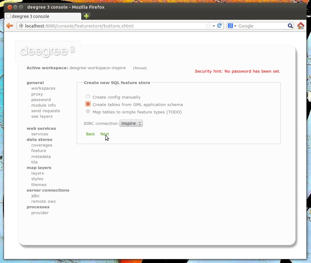
You can now select the GML application schema files to be used. For this walkthrough, tick Addresses.xsd, AdministrativeUnits.xsd and CadastralParcels.xsd (if you select all schema files, hundreds of feature types from INPIRE Annex I will be mapped):
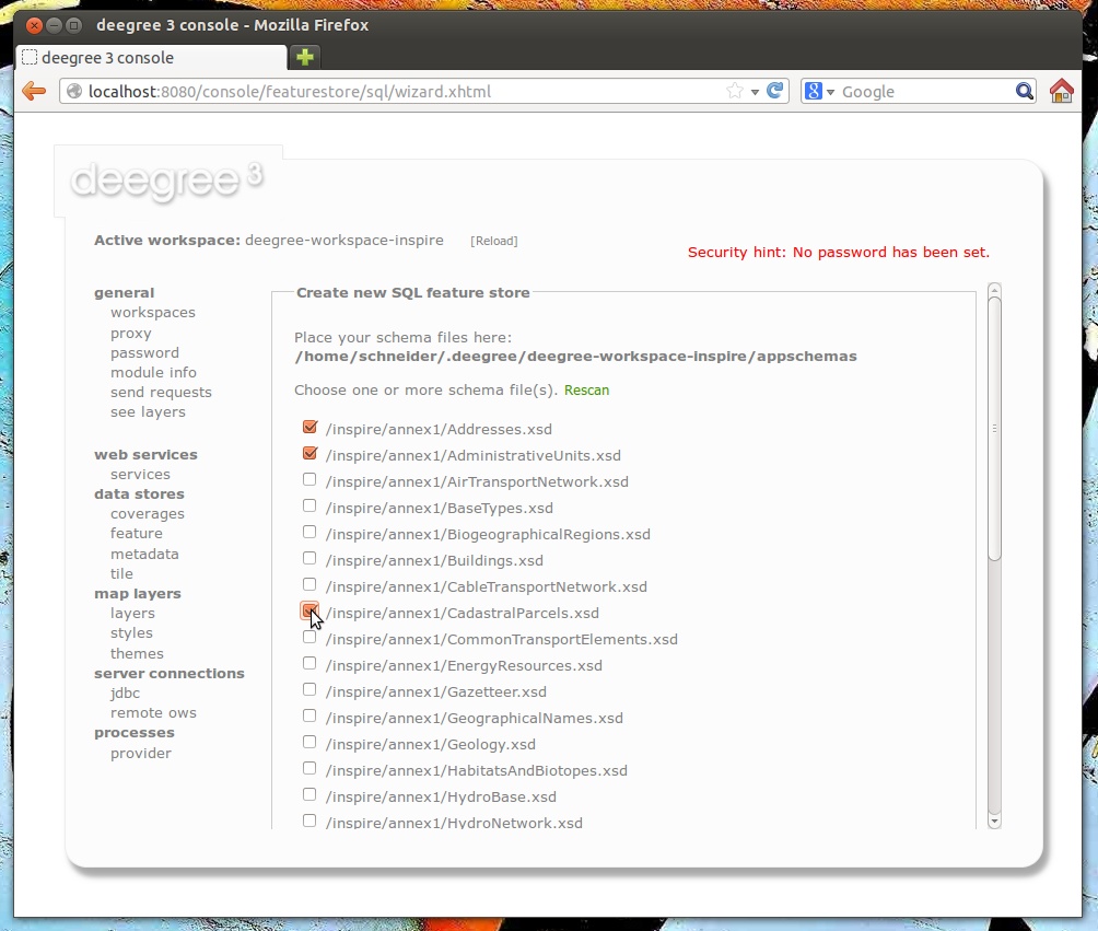
|
Note
|
This view presents any .xsd files that are located below the appschemas/ directory of your deegree workspace. If you want to map any other GML application schema (such as GeoSciML or CityGML), place a copy of the application schema files into the appschemas/ directory (using your favorite method, e.g. a file browser) and click Rescan. You should now have the option to select the files of this application schema in the services console view. |
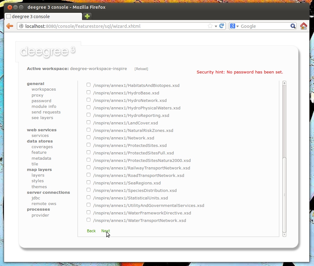
Scroll down and click Next.
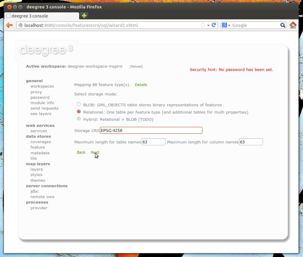
You will be presented with a rough analysis of the feature types contained in the selected GML application schema files. Select "Relational" (you may also select BLOB if your prefer this kind of storage) and enter "EPSG:4258" as storage CRS (this is the code for ETRS89, the recommmended CRS for harmonized INSPIRE datasets). After clicking Next, an SQL feature store configuration will be automatically derived from the application schema:
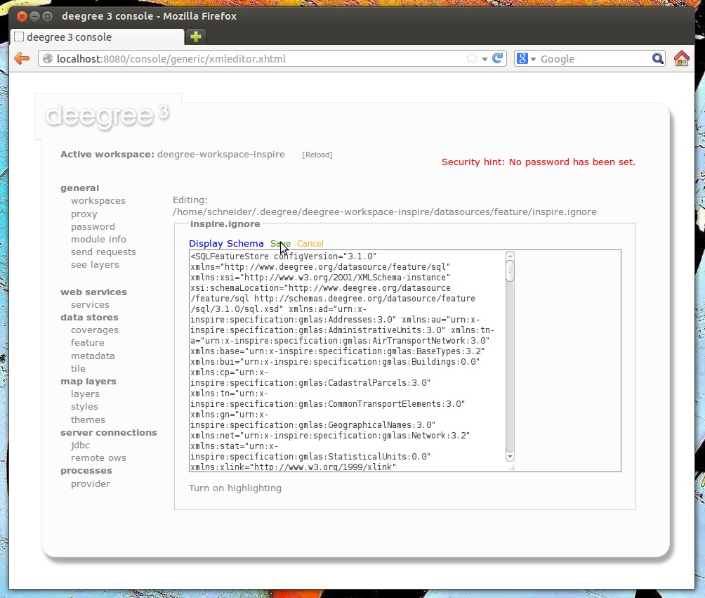
Click Save to store this configuration:
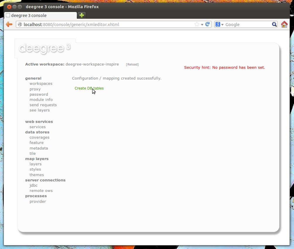
Now, click Create DB tables. You will be presented with an auto-generated SQL script for creating the required tables in the database:
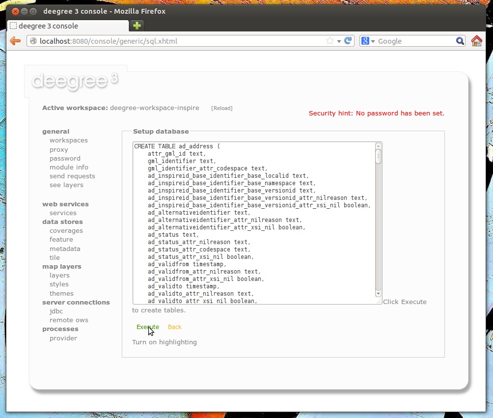
Click Execute. The SQL statements will now be executed against your database and the tables will be created:
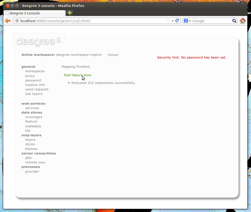
Click Start feature store:
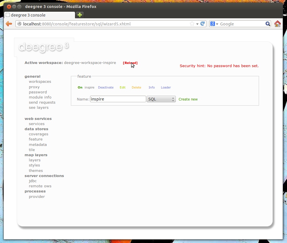
Click Reload to force a reinitialization of the other workspace resources. We’re finished. Features access of the WFS and WMS uses your database now. However, as your database is empty, the WMS will not render anything and the WFS will not return any features when queried. In order to insert some harmonized INSPIRE features, click send requests and select one of the insert requests:
Use the third drop-down menu to select an example request. Entries "Insert_200.xml" or "Insert_110.xml" can be used to insert a small number of INSPIRE Address features using WFS-T insert requests:
Click Send to execute the request. After successful insertion, the database contains a few addresses, and you may want to move back to the layer overview (see layers). If you activate the AD.Address layer, the newly inserted features will be rendered by the deegree WMS (look for them in the area of Enkhuizen):
Of course, you can also perform WFS queries against the database backend, such as requesting of INSPIRE Addresses by street name:
Besides WFS-T requests, there’s another handy option for inserting GML-encoded features. Click data stores → feature to access the feature store view again:

After clicking Loader, you will be presented with a simple view where you can insert a URL of a valid GML dataset:
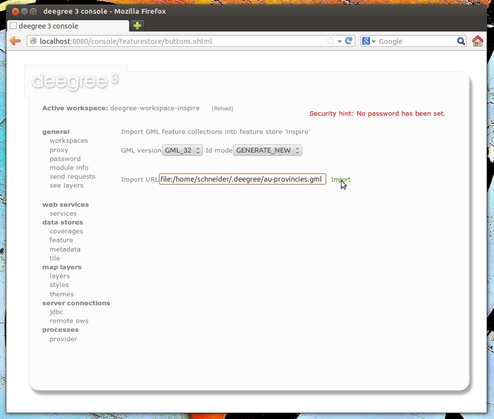
Basically, you can use this view to insert any valid, GML-encoded dataset, as long as it conforms to the application schema. The INSPIRE workspace contains some suitable example datasets, so you may use a file-URL like:
-
file:/home/kelvin/.deegree/deegree-workspace-inspire/data/au-provincies.gml
-
file:/home/kelvin/.deegree/deegree-workspace-inspire/data/au-gemeenten.gml
-
file:/home/kelvin/.deegree/deegree-workspace-inspire/data/au-land.gml
-
file:/home/kelvin/.deegree/deegree-workspace-inspire/data/cadastralparcels-limburg.xml
-
file:/home/kelvin/.deegree/deegree-workspace-inspire/data/cadastralparcels-northholland.xml
|
Tip
|
The above URLs are for a UNIX system with a user named "kelvin". You will need to adapt the URLs to match the location of your workspace directory. |
After entering the URL, click Import:
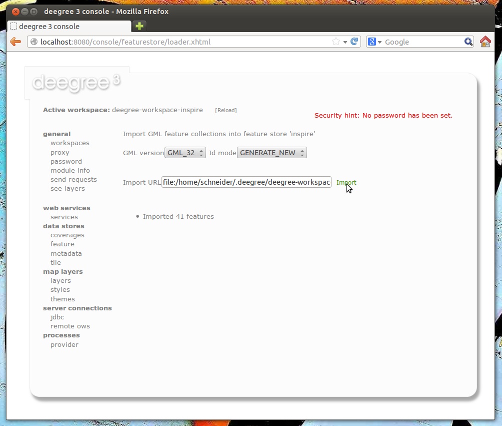
7. Tile stores
Tile stores are resources that provide access to pre-rendered map tiles. The common use case for tile stores is to provide data for tile layers.
The remainder of this chapter describes some relevant terms and the tile store configuration files in detail. You can access this configuration level by clicking on the tile stores link in the administration console. The configuration files are located in the datasources/tile/ directory of the deegree workspace.
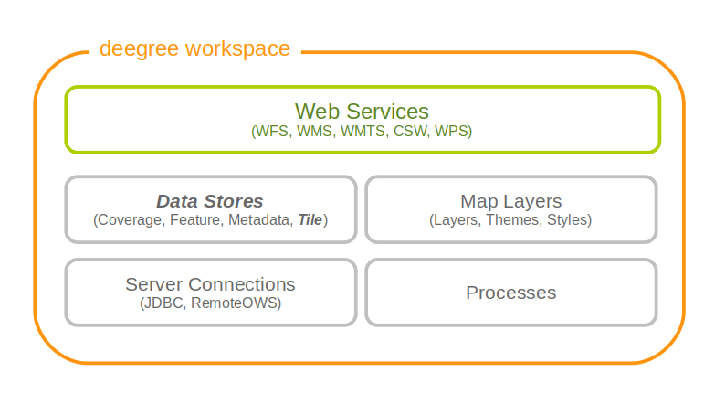
7.1. Tile stores, tile data sets and tile matrix sets
A tile store is what you configure in a single tile store configuration file. It defines one or more (stored) tile data sets. Other resources such as the tile layer configuration usually refer to a specific tile data set from a tile store.
The structure of a tile data set is determined by specifying the identifier of a tile matrix set. Most often, one wants to define tile data sets that conform to a pre-defined tile matrix set. In that case, one only has to provide the tile store configuration file.
The term tile matrix set has been coined deliberately to coincide with the same term from the WMTS specification and refers to structure and spatial properties of the tile matrix. The tile matrix sets (or "quads") from WMTS 1.0.0 and INSPIRE ViewService 3.1 specifications are already predefined, but additional tile matrix sets may be defined as well (see below).
Take note that it is not necessary to provide actual tiles for all tiles defined within the tile matrix set, a tile data set may contain a subset. The only requirement is that you need to fulfill the structure requirements (CRS, size of tiles, position of tiles in world coordinates, scale).
7.1.1. Pre-defined tile matrix sets
The following table lists the tile matrix sets that are pre-defined in deegree:
| Workspace identifier | Name in specification | URN | Specification document |
|---|---|---|---|
globalcrs84scale |
GlobalCRS84Scale |
urn:ogc:def:wkss:OGC:1.0:GlobalCRS84Scale |
OGC WMTS 1.0.0 |
globalcrs84pixel |
GlobalCRS84Pixel |
urn:ogc:def:wkss:OGC:1.0:GlobalCRS84Pixel |
OGC WMTS 1.0.0 |
googlecrs84quad |
GoogleCRS84Quad |
urn:ogc:def:crs:OGC:1.3:CRS84 |
OGC WMTS 1.0.0 |
googlemapscompatible |
GoogleMapsCompatible |
urn:ogc:def:wkss:OGC:1.0:GoogleMapsCompatible |
OGC WMTS 1.0.0 |
inspirecrs84quad |
InspireCRS84Quad |
n/a |
INSPIRE View Service Specification 3.1 |
You can override these standard definitions by placing an appropriately named file into the datasources/tile/tilematrixset/ directory of your workspace. It is recommended to always use lower case file names to avoid confusion.
7.1.2. User-defined tile matrix sets
There are currently two ways to configure tile matrix sets. The first way is to state the structure of the matrices explicitly (described here), the second will extract the structure from a tiled GeoTIFF (BIGTIFF) file (possibly with overlays, described in the GeoTIFF section).
Like everything else in the deegree workspace, defining a tile matrix set means placing a configuration file into a standard location, in this case the datasources/tile/tilematrixset directory.
Let’s have a look at an example for the explicit configuration:
<TileMatrixSet xmlns="http://www.deegree.org/datasource/tile/tilematrixset" configVersion="3.4.0">

  <CRS>urn:ogc:def:crs:OGC:1.3:CRS84</CRS>

  <TileMatrix>
    <Identifier>1e6</Identifier>
    <ScaleDenominator>1e6</ScaleDenominator>
    <TopLeftCorner>-180 84</TopLeftCorner>
    <TileWidth>256</TileWidth>
    <TileHeight>256</TileHeight>
    <MatrixWidth>60000</MatrixWidth>
    <MatrixHeight>50000</MatrixHeight>
  </TileMatrix>
  <TileMatrix>
    <Identifier>2.5e6</Identifier>
    <ScaleDenominator>2.5e6</ScaleDenominator>
    <TopLeftCorner>-180 84</TopLeftCorner>
    <TileWidth>256</TileWidth>
    <TileHeight>256</TileHeight>
    <MatrixWidth>9000</MatrixWidth>
    <MatrixHeight>7000</MatrixHeight>
  </TileMatrix>

</TileMatrixSet>
As you can see, the format is almost identical to the one from the WMTS capabilities documents. A tile matrix set is always defined for a single coordinate system, and contains one or more tile matrices. Each tile matrix has an identifier, a specific scale, an origin (the top left corner in world coordinates), defines a tile width/height in pixels and specifies how many tiles there are in x and y direction.
You do not need to explicitly specify the envelope, it will be calculated automatically from the values you provide. Keep in mind that the conversion between scale and resolution uses the WMTS conversion factor of approx. 111319 in case of degree based coordinate systems (that’s important so the envelope is calculated correctly).
7.2. GeoTIFF tile store
The GeoTIFF tile store can be used to configure tile data sets based on GeoTIFF/BIGTIFF files. The tile store is currently read-only. The requirements for the GeoTIFFs are:
-
it must be created as BIGTIFF (eg. with GDAL using the -co BIGTIFF=YES option)
-
it must be created as a tiled tiff (eg. with GDAL using the -co TILED=YES option)
-
it can contain overviews (it is best to use a recent GDAL version >= 1.8.0, where you can use GDAL_TIFF_OVR_BLOCKSIZE to specify the overview tile size)
-
it is recommended that the overviews contain the same tile size as the main level
-
it must contain the envelope as GeoTIFF tags in the tiff (don’t use world files)
-
it is recommended that the CRS is contained as GeoTIFF tag (but can be overridden in the tile matrix set config, see below)
To make it easy to create a WMTS based on a GeoTIFF, a tile matrix set can be generated from the GeoTIFF structure, using the method described further down. But if you manage to generate your TIFF files to fit the structure of another matrix set it is just as well (the envelope of the GeoTIFF can be a subset of the tile matrix set’s envelope).
Let’s have a look at an example configuration:
<GeoTIFFTileStore xmlns="http://www.deegree.org/datasource/tile/geotiff" configVersion="3.4.0">

  <TileDataSet>
    <Identifier>test</Identifier>
    <TileMatrixSetId>utah</TileMatrixSetId>
    <File>../../data/test.tif</File>
    <ImageFormat>image/png</ImageFormat>
  </TileDataSet>
...
</GeoTIFFTileStore>
(You can define multiple tile data sets within one tile store.)
-
The identifier is optional, and defaults to the base name of the file (in this example test.tif)
-
The tile matrix set id references the tile matrix set
-
obviously you need to point to the GeoTIFF file
-
The image format specifies the output image format, this is relevant if you use the tile store for a WMTS. The default is image/png.
To generate a tile matrix set from the GeoTIFF, put a file into the datasources/tile/tilematrixset/ directory. See how it must look like:
<GeoTIFFTileMatrixSet xmlns="http://www.deegree.org/datasource/tile/tilematrixset/geotiff" configVersion="3.4.0">
  <StorageCRS>EPSG:26912</StorageCRS>
  <File>../../../data/utah.tif</File>
</GeoTIFFTileMatrixSet>
The storage crs is optional if the file contains an appropriate GeoTIFF tag, but can be used to override it.
7.3. File system tile store
The file system tile store can be used to provide tiles from tile cache like directory hierarchies. This tile store is read-write.
Let’s explain the configuration using an example:
<FileSystemTileStore xmlns="http://www.deegree.org/datasource/tile/filesystem" configVersion="3.4.0">

  <TileDataSet>
    <Identifier>layer1</Identifier>
    <TileMatrixSetId>inspirecrs84quad</TileMatrixSetId>
    <TileCacheDiskLayout>
      <LayerDirectory>../../data/tiles/layer1</LayerDirectory>
      <FileType>png</FileType>
    </TileCacheDiskLayout>
  </TileDataSet>
...
</FileSystemTileStore>
(You can define multiple tile data sets within one tile store.)
-
The identifier is optional, default is the layer directory base name
-
The tile matrix set id references the tile matrix set
-
Currently only the tile cache disk layout is supported. Just point to the layer directory and specify the file type of the images (png is recommended, but most image formats are supported)
Please note that if you use external tools to seed the tile store, you need to make sure the resulting structure is compatible. The 00 directory corresponds to the first tile matrix of the referenced tile matrix set, 01 to the second tile matrix and so on.
7.4. Remote WMS tile store
The remote WMS tile store can be used to generate tiles on-the-fly from a WMS service. This tile store is read-only.
While you can configure multiple tile data sets in one remote WMS tile store configuration, they will all be based on one WMS.
Let’s have a look at an example:
<RemoteWMSTileStore xmlns="http://www.deegree.org/datasource/tile/remotewms" configVersion="3.4.0">

  <RemoteWMSId>wms1</RemoteWMSId>

  <TileDataSet>
    <Identifier>satellite</Identifier>
    <TileMatrixSetId>inspirecrs84quad</TileMatrixSetId>
    <OutputFormat>image/png</OutputFormat>
    <RequestParams>
      <Layers>SatelliteProvo</Layers>
      <Styles>default</Styles>
      <Format>image/png</Format>
      <CRS>EPSG:4326</CRS>
    </RequestParams>
  </TileDataSet>
...
</RemoteWMSTileStore>-
The remote wms id is mandatory, and must point to a WMS type remote ows resource
-
The identifier for the tile data sets is mandatory
-
The tile matrix set id references the tile matrix set
-
The output format is relevant if you use this tile data set in a WMTS
-
The request params section specifies parameters to be used in the
- GetMap requests sent to the WMS
-
The layers parameter can be used to specify one or more (comma separated) layers to request
-
The styles parameter must correspond to the layers parameter (works the same like GetMap)
-
The format parameter specifies the image format to request from the WMS
-
The CRS parameter specifies which CRS to use when requesting
Additionally you can specify default and override values for request parameters within the request params block. Just add Parameter tags as described in the Request options layer chapter. The replacing/defaulting currently only works when you configure a WMTS on top of this tile store. GetTile parameters are then mapped to GetMap requests to the backend, and GetFeatureInfo WMTS parameters to GetFeatureInfo WMS parameters on the backend.
7.5. Remote WMTS tile store
The remote WMTS tile store can be used to generate tiles on-the-fly from a WMTS service. This tile store is read-only.
While you can configure multiple tile data sets in one remote WMTS tile store configuration, they will all be based on one WMTS.
Let’s have a look at an example:
<RemoteWMTSTileStore xmlns="http://www.deegree.org/datasource/tile/remotewmts" configVersion="3.4.0">

  <RemoteWMTSId>wmts1</RemoteWMTSId>

  <TileDataSet>
    <Identifier>satellite</Identifier>
    <OutputFormat>image/png</OutputFormat>
    <TileMatrixSetId>EPSG:4326</TileMatrixSetId>
    <RequestParams>
      <Layer>SatelliteProvo</Layer>
      <Style>default</Style>
      <Format>image/png</Format>
      <TileMatrixSet>EPSG:4326</TileMatrixSet>
    </RequestParams>
  </TileDataSet>

</RemoteWMTSTileStore>-
The remote WMTS id is mandatory, and must point to a WMTS type remote OWS resource
-
The identifier for the tile data sets is optional, defaults to the value of the Layer request parameter
-
The output format is relevant if you want to use this tile data set in a WMTS, defaults to the value of the Format request parameter
-
The tile matrix set id references the local tile matrix set you want to use, defaults to the value of the TileMatrixSet request parameter
-
The request params section specifies parameters to be used in the
- GetTile requests sent to the WMTS
-
The layer parameter specifies the layer name to request
-
The style parameter specifies the style name to request
-
The format parameter specifies the image format to request
-
The tile matrix set parameter specifies the tile matrix set to request
Please note that you need a locally configured tile matrix set that corresponds exactly to the tile matrix set of the remote WMTS. They need not have the same identifier(s) (just configure the TileMatrixSetId option if they differ), but the structure (coordinate system, tile size, number of tiles per matrix etc.) needs to be identical.
Additionally you can specify default and override values for request parameters within the request params block. Just add Parameter tags as described in the Request options layer chapter. The replacing/defaulting currently only works when you configure a WMTS on top of this tile store. Please note that the scope attribute allows GetTile and GetFeatureInfo, as GetMap is not supported by WMTS services.
8. Coverage stores
Coverage stores are resources that provide access to raster data. The most common use case for coverage stores is to provide data for coverage layers. You can access this configuration level by clicking the coverage stores link in the service console. The corresponding resource configuration files are located in subdirectory datasources/coverage/ of the active deegree workspace directory.
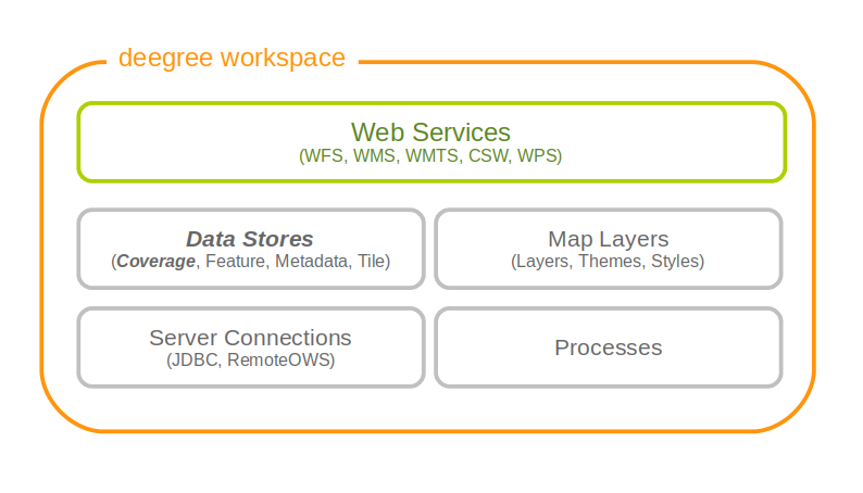
For raster data there are three different possible configurations. One is for <Raster> and one is for <MultiResolutionRaster>. The third possibility is for <Pyramid>. If you are not sure which one to use, you probably want the <Raster> configuration.
8.1. Raster
The most common method to provide coverages with deegree, is to use Raster. With the Raster configuration it is possible to provide single RasterFiles or a complete RasterDirectory directly.
Here are two examples showing RasterFile and RasterDirectory configuration:
<Raster xmlns="http://www.deegree.org/datasource/coverage/raster" xmlns:xsi="http://www.w3.org/2001/XMLSchema-instance" xsi:schemaLocation="http://www.deegree.org/datasource/coverage/raster http://schemas.deegree.org/datasource/coverage/raster/3.0.0/raster.xsd" configVersion="3.4.0" originLocation="outer">
  <StorageCRS>EPSG:26912</StorageCRS>
  <RasterFile>../../../data/utah/raster/dem.tiff</RasterFile>
</Raster>
<Raster xmlns="http://www.deegree.org/datasource/coverage/raster" xmlns:xsi="http://www.w3.org/2001/XMLSchema-instance" xsi:schemaLocation="http://www.deegree.org/datasource/coverage/raster http://schemas.deegree.org/datasource/coverage/raster/3.0.0/raster.xsd" configVersion="3.4.0" originLocation="outer">
<StorageCRS>EPSG:26912</StorageCRS>
<RasterDirectory>../../../data/utah/raster/Satellite_Provo/</RasterDirectory>
</Raster>A Raster can have several attributes:
-
The originLocation attribute can have the values center or outer to declare the pixel origin of the coverage.
-
The nodata attribute can be optionally used to declare a nodata value.
-
The readWorldFiles parameter can have the values true or false to indicate if worlfiles will be read. Default value is true.
-
The StorageCRS paramter is optional but recommended. It contains the EPSG code of the coverage sources.
-
The RasterFile and RasterDirectory parameters contain the path to your coverage sources. The RasterDirectory paramter can additionally have the recursive attribute with true and false as value to declare subdirectories to be included.
|
Warning
|
When using raster files, deegree creates on demand cache files. Depending on the raster data used, the size of the cache files may vary. In individual cases, the use of cache files can be prevented by creating a file <filename>.no-cache or <filename>.no-cache-<level> for whole files or individual levels. Disabling the cache files can have a negative effect on memory consumption. It is recommend to leave the cache enabled if possible. |
8.2. MultiResolutionRaster
A <MultiResolutionRaster> wraps single raster elements and adds a resolution for each raster. This means, depending on the resolution of the map a different raster source is used.
Here is an example for a MultiResolutionRaster:
<MultiResolutionRaster xmlns="http://www.deegree.org/datasource/coverage/raster" xmlns:xsi="http://www.w3.org/2001/XMLSchema-instance" xsi:schemaLocation="http://www.deegree.org/datasource/coverage/raster http://schemas.deegree.org/datasource/coverage/raster/3.0.0/raster.xsd" configVersion="3.4.0" originLocation="outer">
  <StorageCRS>EPSG:26912</StorageCRS>
  <Resolution>
    <Raster configVersion="3.4.0" originLocation="outer" res="1.0">
      <StorageCRS>EPSG:26912</StorageCRS>
      <RasterFile>../../../data/utah/raster/dem.tiff</RasterFile>
    </Raster>
  </Resolution>
  <Resolution>
    <Raster configVersion="3.4.0" res="2.0">
      <StorageCRS>EPSG:26912</StorageCRS>
      <RasterDirectory>../../../data/utah/raster/Satellite_Provo/</RasterDirectory>
    </Raster>
  </Resolution>
</MultiResolutionRaster>-
A MultiResolustionRaster contains at least one Resolution
-
The Raster parameter has a res attribute. Its value is related to the provided resolution.
-
The StorageCRS paramter is optional but recommended. It contains the EPSG code of the coverage sources.
-
All elements and attributes from the Raster configuration can be used for the resolutions.
8.3. Pyramid
A <Pyramid> is used for deegree’s support for raster pyramids. For this, it is required that the raster pyramid must be a GeoTIFF, containing the extent and coordinate system of the data. Overlays must be multiples of 2. This is best tested with source data being processed with GDAL.
8.3.1. Prerequisities for Pyramids
-
Must be a GeoTiff as BigTiff
-
Must be RGB or RGBA
-
CRS must be contained
-
Must be tiled
-
Should have overviews where each overview must consist of 1/2 resolution
The following example shows, how to configure a coverage pyramid:
<Pyramid xmlns="http://www.deegree.org/datasource/coverage/pyramid" xmlns:xsi="http://www.w3.org/2001/XMLSchema-instance" xsi:schemaLocation="http://www.deegree.org/datasource/coverage/pyramid http://schemas.deegree.org/datasource/coverage/raster/3.1.0/pyramid.xsd" configVersion="3.4.0">
  <PyramidFile>data/example.tif</PyramidFile>
  <CRS>EPSG:4326</CRS>
</Pyramid>-
A Pyramid contains a PyramidFile parameter with the path to the pyramid as its value.
-
A Pyramid contains a CRS parameter describing the source CRS of the pyramid as EPSG code.
-
As in Raster, the nodata attribute can be optionally used to declare a nodata value.
8.4. Oracle GeoRaster
A <OracleGeoraster> is used to wrap a connection information to a singe Oracle GeoRaster element inside a Oracle Database.
To be able to use the module it is required that the Oracle GeoRaster libraries are available, see Adding database modules for details.
The following example shows, how to configure a GeoRaster coverage (minmal required options):
<OracleGeoraster configVersion="3.4.0"
xmlns="http://www.deegree.org/datasource/coverage/oraclegeoraster"
xmlns:xsi="http://www.w3.org/2001/XMLSchema-instance"
xsi:schemaLocation="http://www.deegree.org/datasource/coverage/oraclegeoraster http://schemas.deegree.org/datasource/coverage/oraclegeoraster/3.4.0/oraclegeoraster.xsd">]
  <JDBCConnId>oracle</JDBCConnId>
  <StorageCRS>EPSG:25832</StorageCRS>
  <Raster id="17" />
</OracleGeoraster>
The second example shows a complete configuration, which will load faster because no database lookups are required to initiate the coverage store.
<OracleGeoraster configVersion="3.4.0"
  xmlns="http://www.deegree.org/datasource/coverage/oraclegeoraster"
  xmlns:xsi="http://www.w3.org/2001/XMLSchema-instance"
  xsi:schemaLocation="http://www.deegree.org/datasource/coverage/oraclegeoraster http://schemas.deegree.org/datasource/coverage/oraclegeoraster/3.4.0/oraclegeoraster.xsd">

  <JDBCConnId>oracle</JDBCConnId>
  <StorageCRS>EPSG:31468</StorageCRS>

  <StorageBBox>
    <LowerCorner>4508000.0 5652000.0</LowerCorner>
    <UpperCorner>4518000.0 5642000.0</UpperCorner>
  </StorageBBox>

  <Raster id="17" maxLevel="7" rows="10000" columns="10000">
    <Table>RASTER</Table>
    <RDTTable>RASTER_RDT</RDTTable>
    <Column>IMAGE</Column>
  </Raster>

  <Bands>
    <RGB red="1" green="2" blue="3" />
  </Bands>
</OracleGeoraster>
If your GeoRaster coverage only consist in a greyscale coverage or you only want to server a single band you could specifiy the following:
<Bands>
<Single>1</Single>
</Bands>]| Option | Cardinality | Value | Description |
|---|---|---|---|
@id |
1 |
integer |
Identifier of the specified Oracle GeoRaster object |
@maxLevel |
0..1 |
integer |
The number of pyramid levels, specify zero if no pyramid is available |
@rows |
0..1 |
integer |
Number of rows of the GeoRaster |
@columns |
0..1 |
integer |
Number of columns of the GeoRaster |
<Table> |
0..1 |
String |
Defines the name of table name which contains the GeoRaster object |
<RDTTable> |
0..1 |
String |
The name of the corresponding raster data table. |
<Column> |
0..1 |
String |
The column name of the <Table> in which the SDO_GEORASTER is stored |
9. Metadata stores
Metadata stores are data stores that provide access to metadata records. The two common use cases for metadata stores are:
-
Accessing via CSW
-
Providing of metadata for web service resources (TBD)
The remainder of this chapter describes some relevant terms and the metadata store configuration files in detail. You can access this configuration level by clicking on the metadata stores link in the administration console. The configuration files are located in the datasources/metadata/ directory of the deegree workspace.
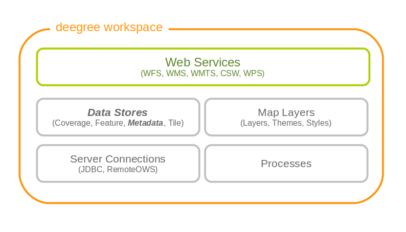
9.1. Memory ISO Metadata store
The memory ISO metadata store implementation is transactional and works file based.
The memory metadata store configuration is defined by schema file http://schemas.deegree.org/datasource/metadata/iso19139/3.4.0/memory.xsd
Memory ISO Metadatastore config (skeleton)
<ISOMemoryMetadataStore
  xmlns="http://www.deegree.org/datasource/metadata/iso19139/memory"
  xmlns:xsi="http://www.w3.org/2001/XMLSchema-instance"
  xsi:schemaLocation="http://www.deegree.org/datasource/metadata/iso19139/memory
  memory.xsd"
  configVersion="3.4.0">
  <!-- [1...n] directory to be used -->
  <ISORecordDirectory>..</ISORecordDirectory>
  <!-- [0...1] directory to be used to insert records -->
  <InsertDirectory>..</InsertDirectory>
</ISOMemoryMetadataStore>
The root element has to be ISOMemoryMetadataStore and the config attribute must be 3.4.0. The only mandatory element is:
-
ISORecordDirectory: A list of directories containing records loaded in the store during start of the store.
To allow insert transactions one optional element must be declared:
-
InsertDirectory: Directory to store inserted records, can be one of the directories declared in the element ISORecordDirectory.
9.2. SQL ISO Metadata store
The SQL metadata store configuration is defined by schema file http://schemas.deegree.org/datasource/metadata/iso19115/3.4.0/iso19115.xsd
SQL ISO Metadatastore config (skeleton)
<?xml version="1.0" encoding="UTF-8"?>
<ISOMetadataStore
  configVersion="3.4.0"
  xmlns="http://www.deegree.org/datasource/metadata/iso19115"
  xmlns:xsi="http://www.w3.org/2001/XMLSchema-instance"
  xsi:schemaLocation="http://www.deegree.org/datasource/metadata/iso19115
  http://schemas.deegree.org/datasource/metadata/iso19115/3.4.0/iso19115.xsd">

  <!-- [1] Identifier of JDBC connection -->
  <JDBCConnId>conn1</JDBCConnId>

  <!-- [0..1] Definition of the Inspectors for checking the metadata for insert
       or update transaction -->
  <Inspectors>

    <!-- [0..1] Checks the fileIdentifier -->
  <FileIdentifierInspector rejectEmpty="true"/>

  </Inspectors>

  <!-- [0..1] Specifies the content of the queryable property 'anyText' -->
  <AnyText>

    <!-- [0..1] Set of XPath-expression (remove line breaks in xpaths!) -->
    <Custom>
      <XPath>/gmd:MD_Metadata/gmd:identificationInfo/
              gmd:MD_DataIdentification/gmd:descriptiveKeywords/gmd:MD_Keywords/
              gmd:keyword/gco:CharacterString</XPath>
      <XPath>/gmd:MD_Metadata/gmd:contact/gmd:CI_ResponsibleParty/
              gmd:individualName/gco:CharacterString</XPath>
    </Custom>

  </AnyText>

</ISOMetadataStore>
The root element has to be ISOMetadataStore and the config attribute must be 3.4.0. The only mandatory element is:
-
JDBCConnId: Id of the JDBC connection to use (see …)
The optional elements are:
-
Inspectors: List of inspectors inspecting a metadataset before inserting. Known inspectors are:
-
FileIdentifierInspector
-
InspireInspector
-
CoupledResourceInspector
-
SchemaValidator
-
NamespaceNormalizer
-
-
AnyText: Configuration of the values searchable by the queryable property AnyText, possible values are:
-
All: all values
-
Core: the core queryable properties (default)
-
Custom: a custom set of properties defined as xpath expressions
-
-
QueryableProperties: Configuration of additional query properties. Detailed informations can be found in the following example:
  ...

  <QueryableProperties>
    <!-- can contain multiple elements 'QueryableProperty' -->
    <!-- set attribute isMultiple="true" if the xpath links
         to a property which can occur multiple times-->
    <QueryableProperty isMultiple="true">
      <!-- configures the xpath to the element which shoud be queryable
           (remove line breaks in xpaths!)-->
      <xpath>//gmd:MD_Metadata/gmd:identificationInfo/
             gmd:MD_DataIdentification/gmd:spatialRepresentationType/
             gmd:MD_SpatialRepresentationTypeCode/@codeListValue</xpath>
      <!-- namespace and name to use in a filter expression, e.g
        <ogc:PropertyName xmlns:apiso="http://www.opengis.net/cat/csw/apiso/1.0">
               apiso:SpatialRepresentationType</ogc:PropertyName> -->
      <name namespace="http://www.opengis.net/cat/csw/apiso/1.0">
           SpatialRepresentationType</name>
      <!-- Name of the column in the table idxt_main where the valus of a record
           should be stored, must be added manually -->
      <column>spatialRepType</column>
    </QueryableProperty>
  </QueryableProperties>
  ...
|
Note
|
If a new queryable property is added or the AnyText value changed the inserted metadata records are not adjusted to this changes! This means for the example above that an existing record with SpatialRepresentationType 'raster' is not found by searching for all records with this type until the record is inserted or updated again! |
9.3. SQL EBRIM/EO Metadata store
TBD
10. Map layers
A (map) layer defines how to combine a data store and a style resource into a map. Each layer resource can be used to define one or more layers. The layers can be used in theme definitions, and depend on various data source and style resources. This chapter assumes you’ve already configured a data source and a style for your layer (although a style is not strictly needed; some layer types can do without, and others can render in a default style when none is given).
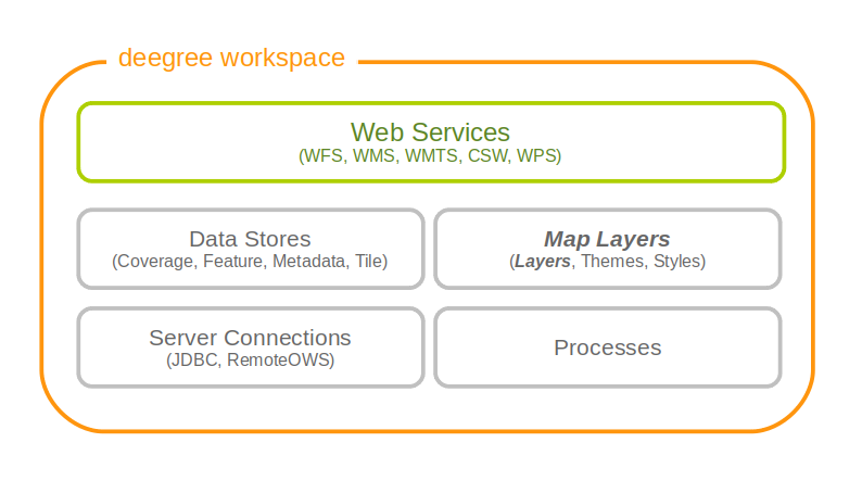
10.1. Common configuration
Most layer configurations follow a similar structure. That’s why some of the common components are exactly the same across configurations (they’re even in common namespaces). In this section these common elements are described first, the subsequent chapters describe the different layer types.
10.1.1. Description metadata
The description section is used to describe textual metadata which occurs in almost all objects. This includes elements such as title, abstract and so on. The format which is being described here is capable of multilingualism, but processing multilingual strings is not supported yet (you can still define it, though).
The commonly used prefix for these elements is d. Let’s have a look at an example:
<d:Title>My Roads Layer</d:Title>
<d:Abstract>This is my roads layer, which I configured myself. I had no help but the deegree webservices handbook.</d:Abstract>
<d:Keywords>
  <d:Keyword>deegree</d:Keyword>
  <d:Keyword>transportation</d:Keyword>
  <d:Type codeSpace='none'>unknown</d:Type>
</d:Keywords>
All elements support the lang attribute to specify the language, and all elements may occur multiple times (including the Keywords element).
10.1.2. Spatial metadata
The spatial metadata is used to describe coordinate systems and envelopes. Typically, the layers can retrieve the native coordinate system and envelope from the data source, but sometimes it may be desirable to define a special extent, or add more coordinate systems. In the example configurations, the prefix s is used for spatial metadata elements, so it is used here as well:
<s:Envelope crs='EPSG:25832'>
  <s:LowerCorner>204485 5204122</s:LowerCorner>
  <s:UpperCorner>1008600 6134557</s:UpperCorner>
</s:Envelope>
<s:CRS>EPSG:25832 EPSG:31466 EPSG:4326</s:CRS>
As you can see, the envelope is specified in a specific CRS. If the attribute is omitted, EPSG:4326 is assumed. The CRS element may include multiple codes, separated by whitespace.
10.1.3. Common layer options
This sections describes a set of common layer options. Not all options make sense for all layers, but most of them do.
The namespace for the elements (newly) defined in this section is commonly bound to the l character. Let’s have a look at the options available:
| Option | Cardinality | Value | Description |
|---|---|---|---|
Name |
1 |
String |
The unique identifier of the layer |
Description |
0..1 |
Several |
The description elements described above |
Spatial metadata |
0..1 |
Several |
The spatial metadata elements described above |
MetadataSetId |
0..1 |
String |
A metadata set id by which this layer is identified |
ScaleDenominators |
0..1 |
Empty |
Used to define scale constraints on the layer |
Dimension |
0..n |
Complex |
Used to configure extra dimensions for the layer |
StyleRef |
0..n |
Complex |
Used to reference one or more styles |
LayerOptions |
0..1 |
Complex |
Used to configure rendering behaviour |
The MetadataSetId is used in the WMS to export a MetadataURL based on a template. Please refer to the WMS configuration for details on how to configure this.
The ScaleDenominators element has min and max attributes which define the constraints in WMS 1.3.0 scale denominators (based on 0.28mm pixel size).
Layer dimensions
The WMS specification supports extra dimensions (besides the spatial extent) for layers, such as elevation, time or other custom dimensions. Since the support must be present at the layer level, this must be configured on the layer in deegree. The Dimension element can have the attributes isTime and isElevation to indicate that you’re defining the standard time/elevation dimension. If none is given, you’ll have to specify the Name element. Let’s see what you can configure here:
| Option | Cardinality | Value | Description |
|---|---|---|---|
Name |
0..1 |
String |
The dimension name, if not elevation or time |
Source |
1 |
String/QName |
The data source of the dimension |
DefaultValue |
0..1 |
String |
Specify a default value to be used, default is none |
MultipleValues |
0..1 |
Boolean |
Whether multiple values are supported, default is false |
NearestValue |
0..1 |
Boolean |
Whether jumping to the nearest value is supported, default is false |
Current |
0..1 |
Boolean |
Whether current is supported for time, default is false |
Units |
0..1 |
String |
What units this dimension uses. Mandatory for non time/elevation |
UnitSymbol |
0..1 |
String |
What unit symbol to use. Mandatory for non time/elevation |
Extent |
1 |
String |
The extent of the dimension |
Please note that for feature layers, the Source element content must be a qualified property name.
To understand how the omission or specification of the various optional elements here affect the WMS protocol behaviour, it is recommended to read up on the WMS 1.3.0 specification. The deegree WMS is going to behave according to what the spec says it must do (what to do in case a default value is available or not etc.). The format for the values and the extent is also identical to that used for requests/in the spec.
Layer styles
You can configure any number of StyleRef elements. Each corresponds to exactly one style store configuration, specified by the subelement StyleStoreId. The only other allowed subelement is the Style element, which can be used to extract/rename specific styles from the style store. If omitted, all styles matching the layers' name are used. Let’s have a look at an example snippet:
<l:StyleRef>
  <l:StyleStoreId>roads_style</l:StyleStoreId>
</l:StyleRef>
Here’s a snippet with Style elements:
PLEASE NOTE: The following mechanisms using StyleName LayerNameRef and StyleNameRef elements will only work with SLD files. Using direct SE styles, the only way to configure styles is the above.
<l:StyleRef>
  <l:StyleStoreId>road_styles</l:StyleStoreId>
  <l:Style>
  ...
  </l:Style>
  <l:Style>
  ...
  </l:Style>
</l:StyleRef>
If a Style element is specified, you must first specify what style you want extracted:
<l:Style>
  <l:StyleName>highways</l:StyleName>
  <l:LayerNameRef>highways</l:LayerNameRef>
  <l:StyleNameRef>highways</l:StyleNameRef>
  ...
</l:Style>
The StyleName specifies the name under which the style will be known in the WMS. The LayerNameRef and StyleNameRef are used to extract the style from the style store.
The next part to configure within the Style element is the legend generation, if you don’t want to use the default legend generated from the rendering style. You can either specify a different style from the style store to use for legend generation, or you can specify an external graphic. Referencing a different legend style is straightforward:
<l:Style>
...
  <l:LegendStyle>
    <l:LayerNameRef>highways</l:LayerNameRef>
    <l:StyleNameRef>highways_legend</l:StyleNameRef>
  </l:LegendStyle>
</l:Style>
With specifying the external graphic, you have the option of referencing a local file, or referencing a remote URL. Specifying a file is straightforward, and will result in the contents of that file being used as legend:
<l:Style>
...
  <l:LegendGraphic>legendimages/mylegend.png</l:LegendGraphic>
</l:Style>
If you specify an HTTP URL instead of a relative path the behaviour is the same by default, the remote images' content is used as legend. If you set the optional attribute outputGetLegendGraphicUrl to false (it’s true by default), the specified URL is written as LegendURL in the WMS capabilities (the behaviour for GetLegendGraphic requests is the same anyway):
<l:Style>
...
  <l:LegendGraphic outputGetLegendGraphicUrl="false">http://legends.acme.com/menu.png</l:LegendGraphic>
</l:Style>
A full example you will find below:
<l:StyleRef>
<l:StyleStoreId>road_styles</l:StyleStoreId>
  <l:Style>
    <l:StyleName>highways</l:StyleName>
    <l:LayerNameRef>highways</l:LayerNameRef>
    <l:StyleNameRef>highways</l:StyleNameRef>
    <l:LegendGraphic outputGetLegendGraphicUrl="false">http://legends.acme.com/menu.png</l:LegendGraphic>
  </l:Style>
  <l:Style>
    <l:LegendStyle>
      <l:LayerNameRef>highways</l:LayerNameRef>
      <l:StyleNameRef>highways_legend</l:StyleNameRef>
    </l:LegendStyle>
  </l:Style>
</l:StyleRef>
Rendering options
The rendering options are basically the same as the WMS layer options. Here’s a copy of the corresponding table for reference:
| Option | Cardinality | String | Description |
|---|---|---|---|
AntiAliasing |
0..1 |
String |
Whether to antialias NONE, TEXT, IMAGE or BOTH, default is BOTH |
RenderingQuality |
0..1 |
String |
Whether to render LOW, NORMAL or HIGH quality, default is HIGH |
Interpolation |
0..1 |
String |
Whether to use BILINEAR, NEARESTNEIGHBOUR or BICUBIC interpolation, default is NEARESTNEIGHBOUR |
MaxFeatures |
0..1 |
Integer |
Maximum number of features to render at once, default is 10000 |
FeatureInfo |
0..1 |
None |
attribute enabled: if false, feature info is disabled (default is true) |
FeatureInfo |
0..1 |
None |
attribute pixelRadius: Number of pixels to consider when doing GetFeatureInfo, default is 1 |
Here is an example snippet:
<l:LayerOptions>
  <l:AntiAliasing>TEXT</l:AntiAliasing>
</l:LayerOptions>
10.2. Feature layers
Feature layers are layers based on a feature store. You can have multiple layers defined in a feature layers configuration, each based on feature types from the same feature store.
You have two choices to configure feature layers. One option is to try to have deegree figure out what layers to configure by itself, the other is to manually define all the layers you want. Having deegree do the configuration automatically has the obvious advantage that the configuration is minimal, with the disadvantage of lacking flexibility.
10.2.1. Auto layers
This configuration only involves to specify what feature store to use, and optionally, what styles. Let’s have a look at an example:
<FeatureLayers xmlns='http://www.deegree.org/layers/feature'
               xmlns:d='http://www.deegree.org/metadata/description'
               xmlns:s='http://www.deegree.org/metadata/spatial'
               xmlns:l='http://www.deegree.org/layers/base'
               configVersion='3.4.0'>

  <AutoLayers>
    <FeatureStoreId>myfeaturestore</FeatureStoreId>
    <StyleStoreId>style1</StyleStoreId>
    <StyleStoreId>style2</StyleStoreId>
  </AutoLayers>

</FeatureLayers>
This will create one layer for each (concrete) feature type in the feature store. If no style stores are configured, the default style will be used for all layers. If style stores are configured, matching styles will be automatically used if available. So if you have a feature type with (local) name Autos, deegree will check all configured style stores for styles identified by layer name Autos and use them, if available. The name Autos will be used as name and title as appropriate, and spatial metadata will be used as available from the feature store.
10.2.2. Manual configuration
The basic structure of a manual configuration looks like this:
<FeatureLayers xmlns='http://www.deegree.org/layers/feature'
               xmlns:d='http://www.deegree.org/metadata/description'
               xmlns:s='http://www.deegree.org/metadata/spatial'
               xmlns:l='http://www.deegree.org/layers/base'
               configVersion='3.4.0'>
  <FeatureStoreId>myfeaturestore</FeatureStoreId>
  <FeatureLayer>
  ...
  </FeatureLayer>
  <FeatureLayer>
  ...
  </FeatureLayer>
</FeatureLayers>
As you can see, the first thing to do is to bind the configuration to a feature store. After that, you can define one or more feature layers.
A feature layer configuration has three optional elements besides the common elements. The FeatureType can be used to restrict a layer to a specific feature type (use a qualified name). The Filter element can be used to specify a filter that applies to the layer globally (use standard OGC filter encoding 1.1.0 ogc:Filter element within):
<FeatureLayer>
  <FeatureType xmlns:app='http://www.deegree.org/app'>app:Roads</FeatureType>
  <Filter>
    <Filter xmlns='http://www.opengis.net/ogc'>
      <PropertyIsEqualTo>
        <PropertyName xmlns:app='http://www.deegree.org/app'>app:type</PropertyName>
        <Literal>123</Literal>
      </PropertyIsEqualTo>
    </Filter>
  </Filter>
  ...
</FeatureLayer>
The third extra option is the SortBy element, which can be used to influence the order in which features are drawn:
<FeatureLayer>
  ...
  <SortBy reverseFeatureInfo="false">
    <SortBy xmlns="http://www.opengis.net/ogc">
      <SortProperty>
        <PropertyName xmlns:app="http://www.deegree.org/app">app:level</PropertyName>
      </SortProperty>
    </SortBy>
  </SortBy>
  ...
</FeatureLayer>
The attribute reverseFeatureInfo is false by default. If set to true, the feature that is drawn first will appear last in a GetFeatureInfo feature collection.
After that the standard options follow, as outlined in the common section.
10.3. Tile layers
Tile layers are based on tile data sets. You can configure an unlimited number of tile layers each based on several different tile data sets within one configuration file.
As you might have guessed, most of the common parameters are ignored for this layer type. Most notably, the style and dimension configuration is ignored.
In most cases, a configuration like the following is sufficient:
<TileLayers xmlns="http://www.deegree.org/layers/tile"
            xmlns:d="http://www.deegree.org/metadata/description"
            xmlns:l="http://www.deegree.org/layers/base"
            configVersion="3.4.0">
  <TileLayer>
    <l:Name>example</l:Name>
    <d:Title>Example INSPIRE layer</d:Title>
    <TileDataSet tileStoreId="sometilestore">roads</TileDataSet>
    <TileDataSet tileStoreId="sometilestore4326">roads</TileDataSet>
  </TileLayer>
</TileLayers>
Just repeat the TileLayer element once for each layer you wish to configure.
Please note that each tile data set needs to be configured with a unique tile matrix set within one layer. It is currently not possible (let’s say it’s not advisable) to configure two tile data sets based on the same tile matrix set within one layer, even if their actual data does not overlap.
If used in a WMTS, the WMTS capabilities will contain only the actually used tile matrix sets, and will contain appropriate links in the layers which have been configured with fitting tile data sets.
10.4. Coverage layers
Coverage layers are based on coverages out of coverage stores. Similar to feature layers, you can choose between an automatic layer setup and a manual configuration.
10.4.1. Auto layers
All you need to configure is the coverage store and an optional style store:
<CoverageLayers xmlns="http://www.deegree.org/layers/coverage"
                xmlns:d="http://www.deegree.org/metadata/description"
                xmlns:l="http://www.deegree.org/layers/base"
                configVersion="3.4.0">
  <AutoLayers>
    <CoverageStoreId>dem</CoverageStoreId>
    <StyleStoreId>heightmap</StyleStoreId>
  </AutoLayers>
</CoverageLayers>
In theory this would add one layer for each coverage in the coverage store, but since only one coverage is supported per coverage store at the moment, only one layer will be the result. If a style store is specified, all styles matching the layer name (the coverage store id) will be available for the layer.
10.4.2. Manual configuration
The manual configuration requires the definition of a coverage store, and one or many coverage layer definitions:
<CoverageLayers xmlns="http://www.deegree.org/layers/coverage"
                xmlns:d="http://www.deegree.org/metadata/description"
                xmlns:l="http://www.deegree.org/layers/base"
                configVersion="3.4.0">
  <CoverageStoreId>dem</CoverageStoreId>
  <CoverageLayer>
  <!-- standard layer options -->
  </CoverageLayer>
</CoverageLayers>
Within the CoverageLayer element you can only define the common layer options. While only one coverage is supported per coverage store, it might still be desirable to define multiple layers based on the store, for example one layer per style.
10.5. Remote WMS layers
Remote WMS layers are based on layers requested from another WMS on the network. In its simplest mode, the remote WMS layer store will provide all layers that the other WMS offers, but you can pick out and restrict the configuration to single layers if you want. The common style and dimension options are not used in this layer configuration.
The remote WMS layer configuration is always based on a single RemoteWMS resource, so the most basic configuration which cascades all available layers looks like this:
<RemoteWMSLayers xmlns="http://www.deegree.org/layers/remotewms" configVersion="3.4.0">
  <RemoteWMSId>d3</RemoteWMSId>
  <!-- more detailed options would follow here -->
</RemoteWMSLayers>
In many cases that’s already sufficient, but if you wish to control the way the requests are being sent, you can specify the RequestOptions. If you want to limit/restrict the layers, you can specify any amount of Layer elements.
10.5.1. Request options
Use the ImageFormat element to indicate which format should be requested from the remote WMS. Set the attribute transparent to false if you don’t want to request transparent images. Default is to request transparent image/png maps:
<RequestOptions>
  <ImageFormat transparent='false'>image/gif</ImageFormat>
</RequestOptions>
The DefaultCRS element can be used to specify the CRS to request. If the useAlways attribute is true, maps are always requested in this format, and transformed if necessary. If set to false (the default), the requested CRS will be requested from the remote service if available. If a requested CRS is not available from the remote service, the value of this option is used, and the resulting image transformed.
The Parameter element can be used (multiple times) to add and/or fix KVP parameter values used in requests to the remote service. The name attribute (which is required) configures which parameter you’re talking about, and the content specifies a default or fixed value. The use and scope attributes can be used to specify how to handle parameters. Have a look at the following table for default and possible values of these attributes:
| Name | Default | Possible values |
|---|---|---|
use |
allowOverride |
allowOverride, fixed |
scope |
All |
GetMap, GetFeatureInfo, All |
Let’s have a look at a couple of examples:
<RequestOptions>
  <Parameter name='BGCOLOR'>#00ff00</Parameter>
<RequestOptions>
This means that all maps are requested with a background color of green, unless the request overrides it. GetFeatureInfo requests will also have the BGCOLOR parameter set, although it makes no difference there.
Another example:
<RequestOptions>
  <Parameter name='USERNAME'>SEC_ADMIN</Parameter>
  <Parameter name='PASSWORD'>JOSE67</Parameter>
</RequestOptions>
In this case all requests will have USERNAME and PASSWORD set to these values. Users can still override these values in requests.
A last example:
<RequestOptions>
  <Parameter scope='GetMap' name='BGCOLOR'>#00ff00</Parameter>
  <Parameter use='fixed' name='USERNAME'>SEC_ADMIN</Parameter>
  <Parameter use='fixed' name='PASSWORD'>JOSE67</Parameter>
</RequestOptions>
Now all GetMap requests will have the USERNAME and PASSWORD parameters hard coded to the configured values, with the BGCOLOR parameter set to green by default, but with the possibility of override by the user. GetFeatureInfo requests will only have the USERNAME and PASSWORD parameters fixed to the configured values.
10.5.2. Layer configuration
The manual configuration allows you to pick out a layer, rename it, and optionally override the _common description and spatial metadata. What you don’t override, will be copied from the source. Let’s look at an example:
<RemoteWMSLayers>
  ...
  <Layer>
    <OriginalName>cite:BasicPolygons</OriginalName>
    <Name>basic_polygons</Name>
    <!-- optionally override description (title, abstract, keywords) -->
    <!-- optionally override envelope, crs -->
    <!-- optionally set layer options -->
  </Layer>
</RemoteWMSLayers>
Please note that once you specify one layer, you’ll need to specify each layer you want to make available. If you want all layers to be available, don’t specify a Layer element. Of course, you can specify as many Layer elements as you like.
11. Map themes
A theme defines a tree like hierarchy, which at each node can contain a number of layers. For people familiar with WMS, a theme is basically a layer tree without the actual layer definition.
In deegree it is used to define a structure with layers to be used in service configurations, notably WMS and WMTS. The concept originated from the WMTS 1.0.0 specification, with a strong hunch that it might be used in subsequent WMS specifications as well (namely WMS 2.0.0).
To configure a theme, you should already have a couple of layers configured. Right now there are two types of theme configurations available. The most commonly used is the 'standard' theme configuration, where you manually configure the structure. Another is a configuration which extracts a theme from a remote WMS resource’s layer tree.
A theme always has exactly one root node (theme). A theme can contain zero or more sub-themes, and zero or more layers.
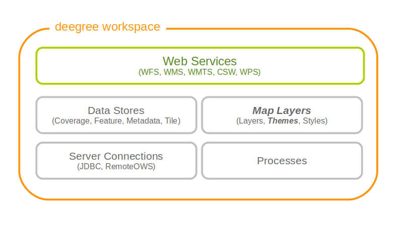
11.1. Standard themes
The standard theme configuration is used to manually configure themes. One configuration can contain one or more themes. A theme configuration makes use of the common description and spatial elements described in the layer chapter. If the metadata is not specified, it will be copied from layers within the same node.
In order to reference layers, the theme configuration needs to know layer stores. That’s why the first thing you need to specify are the layer stores you intend to use:
<Themes configVersion="3.4.0" xmlns="http://www.deegree.org/themes/standard"
                              xmlns:d="http://www.deegree.org/metadata/description"
                              xmlns:s="http://www.deegree.org/metadata/spatial">

  <LayerStoreId>layerstore</LayerStoreId>
  <LayerStoreId>layerstore2</LayerStoreId>
  <Theme>
  ...
  </Theme>
  ...
</Themes>
Let’s have a look at the actual theme configuration. First, you have the choice to give the theme an identifier or not. Then you can specify the description and spatial metadata (only the Title element is mandatory here). If it does not have an identifier, it will not be requestable in the service configuration:
<Theme>
  <Identifier>roads</Identifier>
  <!-- common description elements here -->
  <!-- common spatial metadata elements here -->
  ...
</Theme>
After that, you can add layers and subthemes as required to the theme:
<Theme>
  ...
  <Layer>roads</Layer>
  <Layer layerStore='layerstore2'>highways</Layer>
  <Theme>
    ...
    <Theme>
      ...
    </Theme>
  </Theme>
</Theme>
As you can see, you can optionally specify which layer store a given layer comes from. This can be useful if you have multiple layer stores offering a layer with the same name.
Since the names of the layers are not used when using WMS, this mechanism can be used to combine multiple layers (configuration wise) into one (WMS wise, in deegree terms it would be one theme with multiple layers).
11.2. Remote WMS themes
The remote WMS theme configuration can be used to extract a theme from a remote WMS resource’s layer tree. This is most commonly used when trying to cascade a whole WMS.
The configuration is very simple, you only need to specify the remote WMS resource you want to use, and the layer store from which layers should be extracted:
<RemoteWMSThemes xmlns="http://www.deegree.org/themes/remotewms" configVersion="3.4.0">
  <RemoteWMSId>d3</RemoteWMSId>
  <LayerStoreId>d3</LayerStoreId>
</RemoteWMSThemes>
deegree will automatically add layers to the theme, if a corresponding layer exists in the layer store. In case the layer store is also configured based on the remote WMS used here, there will be a corresponding layer for each requestable layer from the remote WMS.
Using this kind of configuration, you can duplicate a complete WMS using 15 lines of configuration (3 for the remote WMS, 3 for the remote WMS layer store, 4 for the theme and 5 for the WMS).
12. Map styles
Style resources are used to obtain information on how to render geo objects (mostly features, but also coverages) into maps. The most common use case is to reference them from a layer configuration, in order to describe how the layer is to be rendered. This chapter assumes the reader is familiar with basic SLD/SE terms. The style configurations do not depend on any other resource.
In contrast to other deegree configurations the style configurations do not have a custom format. You can use standard SLD or SE documents (1.0.0 and 1.1.0 are supported), with a couple of deegree specific extensions, which are described below. Please refer to the SLD and SE specifications for reference. Additionally this page contains specific examples below.
In deegree terms, each SLD or SE file will create a style store. In case of an SE file (usually beginning at the FeatureTypeStyle or CoverageStyle level) the style store only contains one style, in case of an SLD file the style store may contain multiple styles, each identified by the layer (only NamedLayers make sense here) and the name of the style (only UserStyles make sense) when referenced later.
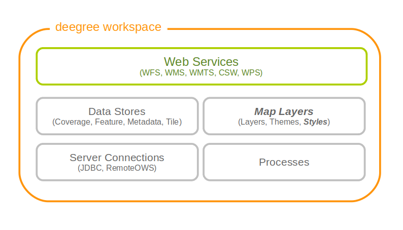
|
Tip
|
When defining styles, take note of the log file. Upon startup the log will warn you about potential problems or errors during parsing, and upon rendering warnings will be emitted when rendering is unsuccessful eg. because you had a typo in a geometry property name. When you’re seeing an empty map when expecting a fancy one, check the log before reporting a bug. deegree will tolerate a lot of syntactical errors in your style files, but you’re more likely to get a good result when your files validate and you have no warnings in the log. |
12.1. Overview
From the point of view of the Symbology Encoding Standard, there are 5 kinds of symbolizations, which can be present in a map image:
-
Point symbolizations
-
Line symbolizations
-
Polygon symbolizations
-
Text symbolizations
-
Raster symbolizations
The first 4 symbolizations usually represent vector feature objects. Raster symbolization is used to visualize raster data. This documentation chapter describes, how those symbolizations can be realized using OGC symbology encoding. It will lead from the underlying basics to some more complex constructions for map visulization.
12.2. Basics
12.2.1. General Layout
The general structure of an SE-Style contains:
<FeatureTypeStyle>
<FeatureTypeName>
<Rule>
It is constructed like this:
<FeatureTypeStyle xmlns="http://www.opengis.net/se" xmlns:ogc="http://www.opengis.net/ogc" xmlns:sed="http://www.deegree.org/se" xmlns:deegreeogc="http://www.deegree.org/ogc" xmlns:plan="http://www.deegree.org/plan" xmlns:xsi="http://www.w3.org/2001/XMLSchema-instance" xsi:schemaLocation="http://www.opengis.net/se http://schemas.opengis.net/se/1.1.0/FeatureStyle.xsd http://www.deegree.org/se http://schemas.deegree.org/se/1.1.0/Symbolizer-deegree.xsd">
    <FeatureTypeName>plan:yourFeatureType</FeatureTypeName>
    <Rule>
        ...
    </Rule>
</FeatureTypeStyle>|
Tip
|
Before you start, always remember that every style is read top-down. So be aware the second <Rule> will overpaint the first one, the third overpaints the second and so on |
12.2.2. Symbolization Rules
Every specific map visualization needs its own symbolization rule. Rules are defined within the <Rule> element. Each rule can consist of at least one symbolizer. Every rule has its own name and description elements. The description elements are used to create the legend caption from it.
Depending on the type of symbolization to create, one of the following symbolizers can be used:
-
<PointSymbolizer>
-
<LineSymbolizer>
-
<PolygonSymbolizer>
-
<TextSymbolizer>
-
<RasterSymbolizer>
Symbolizers can have an uom-attribute (units of measure), which determines the unit of all values set inside the Symbolizer. The following values for UoM are supported within deegree:
-
uom="pixel"
-
uom="meter"
-
uom="mm"
The default value is "pixel".
Within every symbolizer (except rastersymbolizers), a geometry property used for the rendering, can be specified with the <Geometry> element. If there is no geometry specified the first geometry property of the FeatureType will be used.
Each of the (Vector-)Symbolizer-elements has its dimensions, which are described in more detail below:
-
<LineSymbolizer> has only one dimension: the <Stroke>-element (to style the stroke).
-
<PolygonSymbolizer> has two dimensions: the <Stroke> (to sytle the stroke of the polygon) and the <Fill>-element (to style the inside of the polygon).
-
<PointSymbolizer> can also contain both dimensions: the <Stroke> (to style the stroke of the point) and the <Fill>-element (to style the inside of the point).
-
<TextSymbolizer> has three dimensions: the <Label> (to set the property, which is to be styled), the <Font> (to style the font) and the <Fill>-element (to style the inside of the font).
Stroke
To describe a <Stroke>, a number of different <SvgParameter> can be used.
-
name="stroke"⇒ The stroke (color) is defined by the hex color code (e.g. black =⇒ #000000). -
name="opacity"⇒ Opacity can be set by a percentage number, written as decimal (e.g. 0,25 ⇒ 25% opacity). -
name="with"⇒ Wide or thin, set your stroke-width however you want. -
name="linecap"⇒ For linecap (ending) a stroke you can choose the following types: round, edged, square, butt. -
name="linejoin"⇒ Also there are different types of linejoin possibilities: round, mitre, bevel. -
name="dasharray"⇒ The dasharray defines where the stroke is painted and where not (e.g. "1 1" ⇒ - - - ).
<LineSymbolizer uom="meter">
  <Geometry>
    <ogc:PropertyName>layer:position</ogc:PropertyName>
  </Geometry>
  <Stroke>
    <SvgParameter name="stroke">#000000</SvgParameter>
    <SvgParameter name="stroke-opacity">0.5</SvgParameter>
    <SvgParameter name="stroke-width">1</SvgParameter>
    <SvgParameter name="stroke-linecap">round</SvgParameter>
    <SvgParameter name="stroke-linejoin">round</SvgParameter>
    <SvgParameter name="stroke-dasharray">1 1</SvgParameter>
  </Stroke>
</LineSymbolizer>
Fill
For the visualization of polygons, points and texts, the <Fill> element can be used additional to styling the <Stroke>. You can set the following <SvgParameter>:
-
name="fill" (color)
-
name="fill-opacity"
These two <SvgParameter> are working like those from <Stroke>.
<PolygonSymbolizer uom="meter">
  <Geometry>
    <...>
  </Geometry>
  <Fill>
    <SvgParameter name="fill">#000000</SvgParameter>
    <SvgParameter name="fill-opacity">0.5</SvgParameter>
  </Fill>
  <Stroke>
    <...>
  </Stroke>
</PolygonSymbolizer>
Font
For the creation of a <TextSymbolizer>, certain parameters for the displayed text have to be set. Every <TextSymbolizer> needs a <Label> to be specified. The <Font> to be used for the text symbolization can be set with <SvgParameter> elements. These are the possible <SvgParameter>:
-
name="font-family"⇒ Possible types are: e.g. Arial, Times Roman, Sans-Serif -
name="font-weight"⇒ Possible types are: normal, bold, bolder, lighter -
name="font-size"⇒ Possible values are integer values
With a <Fill>-element a color and opacity of the font can be defined. This method is used to show text which is stored in your database.
<TextSymbolizer uom="meter">
  <Geometry>
    <...>
  </Geometry>
  <Label>
    <ogc:PropertyName>layer:displayedProperty</ogc:PropertyName>
  </Label>
  <Font>
    <SvgParameter name="font-family">Arial</SvgParameter>
    <SvgParameter name="font-family">Sans-Serif</SvgParameter>
    <SvgParameter name="font-weight">bold</SvgParameter>
    <SvgParameter name="font-size">3</SvgParameter>
  </Font>
  <Fill>
    <...>
  </Fill>
</TextSymbolizer>
12.2.3. Advanced symbolization
There are numerous possibilities for advanced symbolization. This chapter describes the basic components of advanced map stylings using symbology encoding.
Using Graphics
There are different ways to use graphical symbols as a base for map symbolizations. <Mark> elements can be used to specify well known graphics, <ExternalGraphic> elements can be used to have external graphic files as a base for a symbolization rule.
Mark
With Marks it is possible to use wellkown objects for symboliation as well as user-generated content like SVGs. It is possible to use all of these for <PointSymbolizer>, <LineSymbolizer> and <PolygonSymbolizer>.
For a <PointSymbolizer> the use of a Mark looks like the following:
<PointSymbolizer uom="meter">
  <Geometry>
    ...
  </Geometry>
  <Graphic>
    <Mark>
      ...
For <LineSymbolizer> and <PolygonSymbolizer> it works like this:
<Geometry>
  ...
</Geometry>
<Stroke>
  <GraphicStroke>
    <Graphic>
      <Mark>
...- The following wellknown objects can be used within Marks
-
-
circle
-
triangle
-
star
-
square
-
x =⇒ creates a cross
-
<Mark>
  <WellKnownName>triangle</WellKnownName>
  <Fill>
    ...
  </Fill>
</Mark>
Including an SVG graphic within a mark might look like this:
<Mark>
  <OnlineResource xmlns:xlink="http://www.w3.org/1999/xlink" xlink:type="simple"
    xlink:href="/filepath/symbol.svg" />
  <Format>svg</Format>
  <Fill>
    ...
  </Fill>
  <Stroke>
    ...
  </Stroke>
</Mark>
ExternalGraphic
<ExternalGraphic>-elements can be used to embed graphics, taken from a graphic-file (e.g. SVGs or PNGs). The <OnlineResource> sub-element gives the URL of the graphic-file.
|
Tip
|
Make sure you don’t forget the MIME-type in the <Format>-sub-element (e.g. "image/svg" or "image/png"). |
<Graphic>
  <ExternalGraphic>
    <OnlineResource xmlns:xlink="http://www.w3.org/1999/xlink"
      xlink:type="simple" xlink:href="/filepath/symbol.svg" />
    <Format>image/svg</Format>
  </ExternalGraphic>
 <Size>10</Size>
  ...
</Graphic>
Size
Of course everything has its own <Size>. The size is defined directly after <Mark> or <ExternalGraphic>.
<Mark>
  <WellKnownName>triangle</WellKnownName>
  <Fill>
    <SvgParameter name="fill">#000000</SvgParameter>
  </Fill>
</Mark>
<Size>3</Size>
Gap
It is possible to define Gaps for graphics within <LineSymbolizer> or <PolygonSymbolizer>. For this the <Gap>-element can be used like this:
<GraphicStroke>
  <Graphic>
    <Mark>
      ...
    </Mark>
    ...
  </Graphic>
  <Gap>20</Gap>
</GraphicStroke>l
Rotation
Symbology Encoding enables the possibility to rotate every graphic around its center with the <Rotation>-element. This goes from zero to 360 degrees. The rotation is clockwise unless it’s negative, then it’s counter-clockwise.
<Graphic>
  <Mark>
    ...
  </Mark>
  <Size>3</Size>
  <Rotation>180</Rotation>
</Graphic>
Displacement
The <Displacement>-element allows to paint a graphic displaced from his given position. Negative and positive values are possible. THe displacement must be set via the X and Y displacement elements.
<Graphic>
  <Mark>
    ...
  </Mark>
  ...
  <Displacement>
    <DisplacementX>5</DisplacementX>
    <DisplacementY>5</DisplacementY>
  </Displacement>
</Graphic>
Halo
A nice possibility to highlight your font, is the <Halo>-element. The <Radius>-sub-element defines the size of the border.
<TextSymbolizer uom="meter">
    <Geometry>
        <ogc:PropertyName>xplan:position</ogc:PropertyName>
    </Geometry>
    <Label>
        ...
    </Label>
    <Font>
        ...
    </Font>
    <LabelPlacement>
        ...
    </LabelPlacement>
    <Halo>
        <Radius>1.0</Radius>
        <Fill>
            ...
        </Fill>
    </Halo>
    ...
</TextSymbolizer>
12.3. Using Filters
Within symbolization rules, it is possible to use Filter Encoding expressions. How construct those expressions is explained within the Filter Encoding chapter
12.4. Basic Examples
12.4.1. Point Symbolizer
<FeatureTypeStyle
xmlns="http://www.opengis.net/se"
xmlns:app="http://www.deegree.org/app"
xmlns:ogc="http://www.opengis.net/ogc"
xmlns:sed="http://www.deegree.org/se"
xmlns:deegreeogc="http://www.deegree.org/ogc"
xmlns:xsi="http://www.w3.org/2001/XMLSchema-instance"
xsi:schemaLocation="http://www.opengis.net/se http://schemas.opengis.net/se/1.1.0/FeatureStyle.xsd http://www.deegree.org/se http://schemas.deegree.org/se/1.1.0/Symbolizer-deegree.xsd">
 <Name>Weatherstations</Name>
 <Rule>
    <Name>Weatherstations</Name>
    <Description>
      <Title>Weatherstations in Utah</Title>
    </Description>
    <ogc:Filter>
      <ogc:PropertyIsEqualTo>
        <ogc:PropertyName>SomeProperty</ogc:PropertyName>
        <ogc:Literal>100</ogc:Literal>
      </ogc:PropertyIsEqualTo>
      </ogc:Filter>
      <PointSymbolizer>
        <Graphic>
          <Mark>
            <WellKnownName>square</WellKnownName>
            <Fill>
              <SvgParameter name="fill">#FF0000</SvgParameter>
            </Fill>
            <Stroke>
              <SvgParameter name="stroke">#000000</SvgParameter>
              <SvgParameter name="stroke-width">1</SvgParameter>
            </Stroke>
          </Mark>
          <Size>13</Size>
        </Graphic>
      </PointSymbolizer>
  </Rule>
</FeatureTypeStyle>
12.4.2. Line Symbolizer
<FeatureTypeStyle
xmlns="http://www.opengis.net/se"
xmlns:app="http://www.deegree.org/app"
xmlns:ogc="http://www.opengis.net/ogc"
xmlns:sed="http://www.deegree.org/se"
xmlns:deegreeogc="http://www.deegree.org/ogc"
xmlns:xsi="http://www.w3.org/2001/XMLSchema-instance"
xsi:schemaLocation="http://www.opengis.net/se http://schemas.opengis.net/se/1.1.0/FeatureStyle.xsd http://www.deegree.org/se http://schemas.deegree.org/se/1.1.0/Symbolizer-deegree.xsd">
  <Name>Railroads</Name>
  <Rule>
    <Name>Railroads</Name>
    <LineSymbolizer>
      <Stroke>
        <SvgParameter name="stroke">#000000</SvgParameter>
        <SvgParameter name="stroke-opacity">1.0</SvgParameter>
        <SvgParameter name="stroke-width">0.3</SvgParameter>
      </Stroke>
      <PerpendicularOffset>1.5</PerpendicularOffset>
    </LineSymbolizer>
    <LineSymbolizer>
      <Stroke>
        <SvgParameter name="stroke">#ffffff</SvgParameter>
        <SvgParameter name="stroke-opacity">1.0</SvgParameter>
        <SvgParameter name="stroke-width">1.5</SvgParameter>
      </Stroke>
    </LineSymbolizer>
    <LineSymbolizer>
      <Stroke>
        <SvgParameter name="stroke">#000000</SvgParameter>
        <SvgParameter name="stroke-opacity">1.0</SvgParameter>
        <SvgParameter name="stroke-width">0.3</SvgParameter>
      </Stroke>
      <PerpendicularOffset>-1.5</PerpendicularOffset>
    </LineSymbolizer>
  </Rule>
</FeatureTypeStyle>
12.4.3. Polygon Symbolizer
<FeatureTypeStyle
 xmlns="http://www.opengis.net/se"
 xmlns:app="http://www.deegree.org/app"
 xmlns:ogc="http://www.opengis.net/ogc"
 xmlns:sed="http://www.deegree.org/se"
 xmlns:deegreeogc="http://www.deegree.org/ogc"
 xmlns:xsi="http://www.w3.org/2001/XMLSchema-instance"
 xsi:schemaLocation="http://www.opengis.net/se http://schemas.opengis.net/se/1.1.0/FeatureStyle.xsd http://www.deegree.org/se http://schemas.deegree.org/se/1.1.0/Symbolizer-deegree.xsd">
  <Name>LandslideAreas</Name>
  <Rule>
    <Name>LandslideAreas</Name>
    <Description>
      <Title>LandslideAreas</Title>
    </Description>
    <PolygonSymbolizer>
      <Fill>
        <SvgParameter name="fill">#cc3300</SvgParameter>
        <SvgParameter name="fill-opacity">0.3</SvgParameter>
      </Fill>
      <Stroke>
        <SvgParameter name="stroke">#000000</SvgParameter>
        <SvgParameter name="stroke-opacity">1.0</SvgParameter>
        <SvgParameter name="stroke-width">1</SvgParameter>
      </Stroke>
    </PolygonSymbolizer>
  </Rule>
</FeatureTypeStyle>
12.4.4. Text Symbolizer
<FeatureTypeStyle
 xmlns="http://www.opengis.net/se"
 xmlns:app="http://www.deegree.org/app"
 xmlns:ogc="http://www.opengis.net/ogc"
 xmlns:sed="http://www.deegree.org/se"
 xmlns:deegreeogc="http://www.deegree.org/ogc"
 xmlns:xsi="http://www.w3.org/2001/XMLSchema-instance"
 xsi:schemaLocation="http://www.opengis.net/se http://schemas.opengis.net/se/1.1.0/FeatureStyle.xsd http://www.deegree.org/se http://schemas.deegree.org/se/1.1.0/Symbolizer-deegree.xsd">
  <Name>Municipalities</Name>
  <Rule>
    <Name>Municipalities</Name>
    <Description>
      <Title>Municipalities</Title>
    </Description>
    <MaxScaleDenominator>200000</MaxScaleDenominator>
    <TextSymbolizer>
      <Label>
        <ogc:PropertyName>app:NAME</ogc:PropertyName>
      </Label>
      <Font>
        <SvgParameter name="font-family">Arial</SvgParameter>
        <SvgParameter name="font-family">Sans-Serif</SvgParameter>
        <SvgParameter name="font-weight">bold</SvgParameter>
        <SvgParameter name="font-size">12</SvgParameter>
      </Font>
      <Halo>
        <Radius>1</Radius>
        <Fill>
          <SvgParameter name="fill-opacity">1.0</SvgParameter>
          <SvgParameter name="fill">#fefdC3</SvgParameter>
        </Fill>
      </Halo>
      <Fill>
        <SvgParameter name="fill">#000000</SvgParameter>
      </Fill>
    </TextSymbolizer>
  </Rule>
</FeatureTypeStyle>
12.5. SLD/SE clarifications
This chapter is meant to clarify deegree’s behaviour when using standard SLD/SE constructs.
12.5.1. Perpendicular offset/polygon orientation
For polygon rendering, the orientation is always fixed, and will be corrected if a feature store yields inconsistent geometries. The outer ring is always oriented counter clockwise, inner rings are oriented clockwise.
A positive perpendicular offset setting results in an offset movement in the outer direction, a negative setting moves the offset into the interior. For inner rings the effect is flipped (a positive setting moves into the interior of the inner ring, a negative setting moves into the exterior of the inner ring).
12.5.2. ScaleDenominators
The use of MinScaleDenominators and MaxScaleDenominators within SLD/SE files can easily be misunderstood because of the meaning of a high or a low scale. Therefore, this is clarified here according to the standard. In general the MinScaleDenominator is always a smaller number than the MaxScaleDenominator. The following example explains, how it works:
<MinScaleDenominator>25000</MinScaleDenominator>
<MaxScaleDenominator>50000</MaxScaleDenominator>
This means, that the Symbolizer is being used for scales between 1:25000 and 1:50000.
12.6. deegree specific extensions
deegree supports some extensions of SLD/SE and filter encoding to enable more sophisticated styling. The following sections describe the respective extensions for SLD/SE and filter encoding. For several specific extensions, there is a deegree SE XML Schema.
12.6.1. SLD/SE extensions
Use of TTF files as Mark symbols
You can use TrueType font files to use custom vector symbols in a Mark element:
<Mark>
  <OnlineResource xlink:href="filepath/yousans.ttf" />
  <Format>ttf</Format>
  <MarkIndex>99</MarkIndex>
  <Fill>
    <SvgParameter name="fill">#000000</SvgParameter>
    ...
  </Fill>
  <Stroke>
    <SvgParameter name="stroke-opacity">0</SvgParameter>
    ...
  </Stroke>
</Mark>
To find out what index you need to access, have a look at this post on the mailinglist which explains it very well.
Label AutoPlacement
deegree has an option for SE LabelPlacement to automatically place labels on the map. To enable AutoPlacement, you can simply set the "auto" attribute to "true".
<LabelPlacement>
  <PointPlacement auto="true">
    <Displacement>
      <DisplacementX>0</DisplacementX>
      <DisplacementY>0</DisplacementY>
    </Displacement>
    <Rotation>0</Rotation>
  </PointPlacement>
</LabelPlacement>|
Tip
|
AutoPlacement for labels only works for PointPlacement. AutoPlacement for LinePlacement is not implemented yet. |
LinePlacement extensions
There are additional deegree specific LinePlacement parameters available to enable more sophisticated text rendering along lines:
| Option | Value | Default | Description |
|---|---|---|---|
PreventUpsideDown |
Boolean |
false |
Avoids upside down placement of text |
Center |
Boolean |
false |
Places the text in the center of the line |
WordWise |
Boolean |
true |
Tries to place individual words instead of individual characters |
<LinePlacement>
    <IsRepeated>false</IsRepeated>
    <InitialGap>10</InitialGap>
    <PreventUpsideDown>true</PreventUpsideDown>
    <Center>true</Center>
    <WordWise>false</WordWise>
</LinePlacement>
ExternalGraphic extensions
deegree extends the OnlineResource element of ExternalGraphics to support ogc:Expressions as child elements. Example:
<ExternalGraphic>
  <OnlineResource>
      <ogc:PropertyName>app:icon</ogc:PropertyName>
  </OnlineResource>
  <Format>image/svg</Format>
</ExternalGraphic>
12.6.2. SE & FE Functions
There are a couple of deegree specific functions which can be expressed as standard OGC function expressions in SLD/SE. Additionally deegree has support for all the unctions defined within the SE standard.
FormatNumber
This function is needed to format number attributes. It can be used like in the following example:
<FormatNumber xmlns:ogc="http://www.opengis.net/ogc" xmlns:app="http://www.deegree.org/app" xmlns="http://www.opengis.net/se" fallbackValue="">
  <NumericValue>
    <ogc:PropertyName>app:SHAPE_LEN</ogc:PropertyName>
  </NumericValue>
  <Pattern>############.00</Pattern>
</FormatNumber>
FormatDate
This function is fully supported, although not fully tested with all available schema types mentioned in the spec.
<FormatDate xmlns:ogc="http://www.opengis.net/ogc" xmlns:app="http://www.deegree.org/app" xmlns="http://www.opengis.net/se" fallbackValue="">
  <DateValue>
    <ogc:PropertyName>app:TIMESTAMP</ogc:PropertyName>
  </DateValue>
  <Pattern>DD</Pattern>
</FormatDate>
ChangeCase
This function is used to change the case of property values.
<ChangeCase xmlns:ogc="http://www.opengis.net/ogc" xmlns:app="http://www.deegree.org/app" xmlns="http://www.opengis.net/se" fallbackValue="" direction="toUpper">
  <StringValue>
    <ogc:PropertyName>app:text</ogc:PropertyName>
  </StringValue>
</ChangeCase>
Concatenate
With the concatenate function it is possible to merge the values of more than one property to a chain.
<Concatenate xmlns:ogc="http://www.opengis.net/ogc" xmlns:app="http://www.deegree.org/app" xmlns="http://www.opengis.net/se" fallbackValue="">
  <StringValue>
    <ogc:PropertyName>app:text1</ogc:PropertyName>
  </StringValue>
  <StringValue>
    <ogc:PropertyName>app:text2</ogc:PropertyName>
  </StringValue>
  <StringValue>
    <ogc:PropertyName>app:text3</ogc:PropertyName>
  </StringValue>
</Concatenate>
Trim
The trim function is used to trim string property values.
<Trim xmlns:ogc="http://www.opengis.net/ogc" xmlns:app="http://www.deegree.org/app" xmlns="http://www.opengis.net/se" fallbackValue="" stripOffPosition="both">
  <StringValue>
    <ogc:PropertyName>app:text</ogc:PropertyName>
  </StringValue>
</Trim>
StringLength
With the StringLength function it is possible to calculate the length of string property values.
<StringLength xmlns:ogc="http://www.opengis.net/ogc" xmlns:app="http://www.deegree.org/app" xmlns="http://www.opengis.net/se" fallbackValue="">
  <StringValue>
    <ogc:PropertyName>app:text</ogc:PropertyName>
  </StringValue>
</StringLength>
Substring
With the substring function it is possible to only get a specific substring of a string property.
<Substring xmlns:ogc="http://www.opengis.net/ogc" xmlns:app="http://www.deegree.org/app" xmlns="http://www.opengis.net/se" fallbackValue="">
  <StringValue>
    <ogc:PropertyName>app:text</ogc:PropertyName>
  </StringValue>
  <Position>1</Position>
  <Length>
    <ogc:Sub>
      <StringPosition fallbackValue="" searchDirection="frontToBack">
        <LookupString>-</LookupString>
        <StringValue>
          <ogc:PropertyName>app:text</ogc:PropertyName>
        </StringValue>
      </StringPosition>
      <ogc:Literal>1</ogc:Literal>
    </ogc:Sub>
  </Length>
</Substring>
StringPosition
The StringPosition function is made to get the literal at a specific position from a string property.
<StringPosition xmlns:app="http://www.deegree.org/app" xmlns="http://www.opengis.net/se" fallbackValue="" searchDirection="frontToBack">
  <LookupString>-</LookupString>
  <StringValue>
    <ogc:PropertyName xmlns:ogc="http://www.opengis.net/ogc">app:text</ogc:PropertyName>
  </StringValue>
</StringPosition>
Categorize, Interpolate, Recode
These functions can operate both on alphanumeric properties of features and on raster data. For color values we extended the syntax a bit to allow for an alpha channel: #99ff0000 is a red value with an alpha value of 0x99. This allows the user to create eg. an interpolation from completely transparent to a completely opaque color value. To work on raster data you’ll have to replace the PropertyName values with Rasterdata.
For Interpolate only linear interpolation is currently supported.
<Categorize xmlns:app="http://www.deegree.org/app" xmlns="http://www.opengis.net/se" xmlns:ogc="http://www.opengis.net/ogc" fallbackValue="#fefdC3">
  <LookupValue>
    <ogc:PropertyName>app:POP2000</ogc:PropertyName>
  </LookupValue>
  <Value>#FFE9D8</Value>
  <Threshold>1000</Threshold>
  <Value>#FBCFAC</Value>
  <Threshold>10000</Threshold>
  <Value>#FAAC6F</Value>
  <Threshold>25000</Threshold>
  <Value>#FD913D</Value>
  <Threshold>100000</Threshold>
  <Value>#FF7000</Value>
</Categorize>
<Interpolate xmlns:ogc="http://www.opengis.net/ogc" xmlns:app="http://www.deegree.org/app" xmlns="http://www.opengis.net/se" fallbackValue="#005C29" method="color">
<LookupValue>
<ogc:PropertyName>app:CODE</ogc:PropertyName>
</LookupValue>
<InterpolationPoint>
<Data>-1</Data>
<Value>#005C29</Value>
</InterpolationPoint>
<InterpolationPoint>
<Data>100</Data>
<Value>#067A3A</Value>
</InterpolationPoint>
<InterpolationPoint>
<Data>300</Data>
<Value>#03A64C</Value>
</InterpolationPoint>
<InterpolationPoint>
<Data>500</Data>
<Value>#00CF5D</Value>
</InterpolationPoint>
<InterpolationPoint>
<Data>1000</Data>
<Value>#ffffff</Value>
</InterpolationPoint>
</Interpolate><Recode xmlns:app="http://www.deegree.org/app" xmlns="http://www.opengis.net/se" fallbackValue="">
<LookupValue>
<ogc:PropertyName>app:code</ogc:PropertyName>
</LookupValue>
<MapItem>
<Data>1000</Data>
<Value>water</Value>
</MapItem>
<MapItem>
<Data>2000</Data>
<Value>nuclear</Value>
</MapItem>
<MapItem>
<Data>3000</Data>
<Value>solar</Value>
</MapItem>
<MapItem>
<Data>4000</Data>
<Value>wind</Value>
</MapItem>
</Recode>General XPath functions
Many useful things can be done by simply using standard XPath 1.0 functions in PropertyName elements.
Access the (local) name of an element (e.g. the name of a referenced feature / subfeature).
<PropertyName xmlns:app="http://www.deegree.org/app">app:subfeature/*/local-name()</PropertyName>13. Filter Encoding
deegree makes extensive use of the OGC Filter Encoding standard. Within deegree there are implementations of the versions 1.1.0 and 2.0.0 of this standards and several extensions and additional functions. This chapter is meant to explain the filter capabilities of deegree which can be used within Map styles and Web Feature Service (WFS) requests.
13.1. Filter Operators
The purpose of FE is to have a standardized way for defining selection criteria on data. This requires the definition of operators for the creation of filter expressions. Within this section, the supported operators are explained. Additionally there is information about deegree specific behaviour. Depending on the version of FE, syntax may differ. In the following, FE 1.1.0 syntax is used.
13.1.1. Arithmetic operators
FE enables the use of the following arithmetic operators:
-
Add: used for addition -
Sub: used for substraction -
Mul: used for multiplication -
Div: used for division
Example:
<Add>
  <PropertyName>app:ID</PropertyName>
  <Literal>15</Literal>
</Add>
13.1.2. Logical operators
FE enables the use of the following logical operators:
-
And: Links two conditions with AND -
Or: links two conditions with OR -
Not: negates a condition
Example:
<Not>
  <PropertyName>app:ID</PropertyName>
  <Literal>15</Literal>
</Not>
13.1.3. Comparison operators
deegree has implementations for the following list of comparison operators:
-
PropertyIsEqualTo: Evaluates if a property value equals to another value. -
PropertyIsNotEqualTo: Evaluates if a property value differs from another value. -
PropertyIsLessThan: Evaluates if a property value is smaller than another value. -
PropertyIsGreaterThan: Evaluates if a property value is greater than another value. -
PropertyIsLessThanOrEqualTo: Evaluates if a property value is smaller than or equal to another value. -
PropertyIsGreaterThanOrEqualTo: Evaluates if a property value is greater than or euqal to another value. -
PropertyIsLike: Evaluates if a property value is like another value. It compares string values which each other. -
PropertyIsNull: Evaluates if a property value is NULL. -
PropertyIsBetween: Evaluates if a property value is between 2 defined values.
Example:
<PropertyIsEqualTo>
  <PropertyName>SomeProperty</PropertyName>
  <Literal>100</Literal>
</PropertyIsEqualTo>
13.1.4. Spatial operators
With deegree you can make use of the following spatial operators:
-
Equals: Evaluates if geometries are identical -
Disjoin: Evaluates if geometries are spatially disjoined -
Touches: Evaluates if geometries are spatially touching -
Within: Evaluates if a geometry is spatially within another -
Overlaps: Evaluates if geometries are spatially overlapping -
Crosses: Evaluates if geometries are spatially crossing -
Intersects: Evaluates if geometries are spatially intersecting. This is meant as the opposite of disjoin. -
Contains: Evaluates if a geometry spatially contains another. -
DWithin: Evaluates if a geometry is within a specific distance to another. -
Beyond: Evaluates if a geometry is beyond a specific distance to another. -
BBOX: Evaluates if a geometry spatially intersects with a given bounding box.
Example:
<Overlaps>
  <PropertyName>Geometry</PropertyName>
  <gml:Polygon srsName="EPSG:4258">
    <gml:outerBoundaryIs>
      <gml:LinearRing>
        <gml:posList> ... </gml:posList>
      </gml:LinearRing>
    </gml:outerBoundaryIs>
  </gml:Polygon>
</Overlaps>|
Tip
|
For further reading on spatial operators, please refer to the OGC Simple Features Specification For SQL. |
13.2. Filter expressions
For the use within map styles or WFS requests, filter expressions can be constructed from the above operators to select specific data. This section gives some examples for the use of such filter expressions.
13.2.1. Simple filter expressions
Comparative filter expression
<Filter>
  <PropertyIsEqualTo>
    <PropertyName>SomeProperty</PropertyName>
    <Literal>100</Literal>
  </PropertyIsEqualTo>
</Filter>
This filter expressions shows, how filter expressions with a comparative filter are constructed. In the example above, the property SomeProperty is evaluated, if it equals to the value of "100".
Spatial filter expression
<Filter>
  <Overlaps>
    <PropertyName>Geometry</PropertyName>
    <gml:Polygon srsName="EPSG:4258">
      <gml:outerBoundaryIs>
        <gml:LinearRing>
          <gml:posList> ... </gml:posList>
        </gml:LinearRing>
      </gml:outerBoundaryIs>
    </gml:Polygon>
  </Overlaps>
</Filter>
This filter expressions shows, how filter expressions with a spatial filter are constructed. In this example, the defined filter looks up, if the property geometry overlaps with the defined polygon of "…" (geometry values removed for better readability).
13.2.2. Advanced filter expressions
Multiple filter operators
<Filter>
  <And>
    <PropertyIsLessThan>
      <PropertyName>DEPTH</PropertyName>
      <Literal>30</Literal>
    </PropertyIsLessThan>
    <Not>
      <Disjoint>
        <PropertyName>Geometry</PropertyName>
        <gml:Envelope srsName="EPSG:4258">
          <gml:lowerCorner>13.0983 31.5899</gml:lowerCorner>
          <gml:upperCorner>35.5472 42.8143</gml:upperCorner>
        </gml:Envelope>
      </Disjoint>
    </Not>
  </And>
</Filter>
This more complex filter expressions shows, how to make use of combinations of filter operators. THe given filter expression evaluates if the value of the property DEPTH is smaller than "30" and if the geometry property named Geometry is spatially disjoint with the given envelope.
PropertyIsLike with a function
<fes:Filter xmlns:fes="http://www.opengis.net/fes/2.0">
  <fes:PropertyIsLike wildCard="*" singleChar="#" escapeChar="!">
    <fes:ValueReference>name</fes:ValueReference>
    <fes:Function name="normalize">
      <fes:Literal>FALkenstrasse</fes:Literal>
    </fes:Function>
  </fes:PropertyIsLike>
</fes:Filter>
This example shows, how functions can be used within filter expressions. Within the given example, the "name" property is evaluated, if it is like the Literal FAlkenstrasse. Using a function for the evaluation of the Literal means, that the value is processed with the function before the filter operator handles it. In the concrete case this means a normalization of the value (Which is not usable by default with deegree).
|
Tip
|
Please note, the use of functions within PropertyIsLike filter operators is only possible with FE 2.0. This is the reason for the FE 2.0 notation. |
13.2.3. Filter expressions on xlink:href attributes
Example for filtering on xlink:href attributes:
<fes:Filter xmlns:fes="http://www.opengis.net/fes/2.0" xmlns:xlink="http://www.w3.org/1999/xlink">
  <fes:PropertyIsEqualTo>
    <fes:PropertyName>property/@xlink:href</fes:PropertyName>
    <fes:Literal>100</fes:Literal>
  </fes:PropertyIsEqualTo>
</fes:Filter>
deegree applies the filter to the static value of the attribute. This just works if the feature store is configured a certain way. For example, this can be useful if a user wants to filter on INSPIRE codelists.
Chapter Mapping strategies for xlink:href attributes describes how the configuration of the feature store is done and provides further details regarding usage.
13.3. Custom FE functions
Besides the filter capabilities described above, FE defines Functions to be used within filter expressions. deegree offers the capability to use a nice set of custom FE functions for different purposes. These are explained within the following chapter.
13.3.1. Area
The area function is the first in a row of custom geometry functions which can be used within deegree. With the area function it is possible to get the area of a geometry property. If multiple geometry nodes are selected, multiple area values are calculated.
<Function xmlns:app="http://www.deegree.org/app" xmlns="http://www.opengis.net/ogc" name="Area">
  <PropertyName>app:geometry</PropertyName>
</Function>
13.3.2. Length
This function calculates the length of a linestring/perimeter of a polygon. If multiple geometry nodes are selected, multiple length values are calculated.
<Function xmlns:app="http://www.deegree.org/app" xmlns="http://www.opengis.net/ogc" name="Length">
  <PropertyName>app:geometry</PropertyName>
</Function>
13.3.3. Centroid
This function calculates the centroid of a polygon. If multiple geometry nodes are selected, multiple centroids are calculated.
<Function xmlns:app="http://www.deegree.org/app" xmlns="http://www.opengis.net/ogc" name="Centroid">
  <PropertyName>app:geometry</PropertyName>
</Function>
13.3.4. InteriorPoint
This function calculates an interior point within a polygon. If multiple geometry nodes are selected, multiple centroids are calculated. Useful to place text on a point within a polygon (centroids may not actually be a point on the polygon).
<Function xmlns:app="http://www.deegree.org/app" xmlns="http://www.opengis.net/ogc" name="InteriorPoint">
  <PropertyName>app:geometry</PropertyName>
</Function>
13.3.5. IsPoint, IsCurve, IsSurface
Takes one parameter, which must evaluate to exactly one geometry node.
This function returns true, if the geometry is a point/multipoint, curve/multicurve or surface/multisurface, respectively.
<Function xmlns:app="http://www.deegree.org/app" xmlns="http://www.opengis.net/ogc" name="IsCurve">
  <PropertyName>app:geometry</PropertyName>
</Function>
13.3.6. GeometryFromWKT
Useful to create a constant geometry valued expression.
<Function xmlns="http://www.opengis.net/ogc" name="GeometryFromWKT">
  <Literal>EPSG:4326</Literal>
  <Literal>POINT(0.6 0.7)</Literal>
</Function>
13.3.7. MoveGeometry
Useful to displace geometries by a certain value in x and/or y direction.
To shift 20 geometry units in y direction:
<Function xmlns:app="http://www.deegree.org/app" xmlns="http://www.opengis.net/ogc" name="MoveGeometry">
  <PropertyName>app:geometry</PropertyName>
  <Literal>0</Literal>
  <Literal>20</Literal>
</Function>
13.3.8. iDiv
Integer division discarding the remainder.
<Function xmlns:app="http://www.deegree.org/app" xmlns="http://www.opengis.net/ogc" name="idiv">
  <PropertyName>app:count</PropertyName>
  <Literal>20</Literal>
</Function>
13.3.9. iMod
Integer division resulting in the remainder only.
<Function xmlns="http://www.opengis.net/ogc" name="ExtraProp">
  <Literal>planArt</Literal>
</Function>
13.3.10. ExtraProp
Access extra (hidden) properties attached to feature objects. The availability of such properties depends on the loading/storage mechanism used.
<Function xmlns="http://www.opengis.net/ogc" name="ExtraProp">
  <Literal>planArt</Literal>
</Function>
13.3.11. GetCurrentScale
The GetCurrentScale function takes no arguments, and dynamically provides you with the value of the current map scale denominator (only to be used in GetMap requests!). The scale denominator will be adapted to any custom pixel size you may be using in your request, and is the same scale denominator the WMS uses internally for filtering out layers/style rules.
Let’s have a look at an example:
...
<sld:SvgParameter name="stroke-width">
  <ogc:Function name="idiv">
    <ogc:Literal>500000</ogc:Literal>
    <ogc:Function name="GetCurrentScale" />
  </ogc:Function>
</sld:SvgParameter>
...
In this case, the stroke width will be one pixel for scales around 500000, and will get bigger as you zoom in (and the scale denominator gets smaller). Scale denominators above 500000 will yield invisible strokes with a width of zero.
13.3.12. env
The env function takes two parameters and makes it possible to
provide name/value pairs to styles, so that more dynamic styles
are possible.
<Function xmlns="http://www.opengis.net/ogc" name="env">
  <Literal>size</Literal>
  <Literal>42</Literal>
</Function>
These paris can be passed as env parameter alongside the usual
GetMap request parameters. Multiple name:value pairs have to be
separated by semicolons (…&env=size:33;color:FF0000&…).
The second parameter must be the default value that is returned if no pair with the specified name was found.
The following parameters are predefined and cannot be passed:
| Name | Type | Description |
|---|---|---|
wms_bbox |
Envelope |
envelope (GetMap request) |
wms_crs |
ICRS |
coordinate system (GetMap request) |
wms_srs |
String |
coordinate system name (GetMap request) |
wms_width |
Integer |
width in pixel (GetMap request) |
wms_height |
Integer |
height in pixle (GetMap request) |
wms_scale_denominator |
Double |
scale (GetMap request) |
14. Server connections
Server connections are workspace resources that provide connections to remote services. These connections can then be used by other workspace resources. Some common example use cases:
-
JDBC connection: Used by SQL feature stores to access the database that stores the feature data
-
JDBC connection: Used by SQL ISO metadata stores to access the database that stores the metadata records
-
WMS connection: Used by remote WMS layers to access remote WMS
-
WMS connection: Used by remote WMS tile stores to access remote WMS
-
WMTS connection: Used by remote WMTS tile stores to access remote WMTS
There are currently two categories of server connection resources, JDBC connections (to connect to SQL databases) and remote OWS connections (to connect to other OGC webservices).
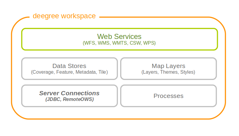
14.1. JDBC connections
These resources define connections to SQL databases, such as PostgreSQL/PostGIS, Oracle Spatial or Microsoft SQL Server.
deegree currently supports the following backends:
-
PostgreSQL 9.4, 9.5, 9.6 with PostGIS extension 2.3, 2.4, 2.5
-
Oracle Spatial 12c
-
Microsoft SQL Server 2012
|
Tip
|
If you want to use Oracle Spatial or Microsoft SQL Server, you will need to add additional modules first. This is described in Adding database modules. |
|
Note
|
By default, deegree webservices includes JDBC drivers for connecting to PostgreSQL and Derby databases. If you want to make a connection to other SQL databases (e.g. Oracle), you will need to add a compatible JDBC driver manually. This is described in Adding Oracle support. |
14.1.1. Minimal configuration example (PostgreSQL)
This example defines a basic connection pool for a PostgreSQL/PostGIS database:
<DataSourceConnectionProvider configVersion="3.4.0"
  xmlns="http://www.deegree.org/connectionprovider/datasource" xmlns:xsi="http://www.w3.org/2001/XMLSchema-instance"
  xsi:schemaLocation="http://www.deegree.org/connectionprovider/datasource http://schemas.deegree.org/jdbc/datasource/3.4.0/datasource.xsd">

  <!-- Creation / lookup of javax.sql.DataSource instance -->
  <DataSource javaClass="org.apache.commons.dbcp.BasicDataSource" />

  <!-- Configuration of DataSource properties -->
  <Property name="driverClassName" value="org.postgresql.Driver" />
  <Property name="url" value="jdbc:postgresql://localhost/deegree-db" />
  <Property name="username" value="kelvin" />
  <Property name="password" value="s3cr3t" />
  <Property name="maxActive" value="10" />

</DataSourceConnectionProvider>-
The DataSource object uses Java class org.apache.commons.dbcp.BasicDataSource (a connection pool class provided by Apache Commons DBCP.). If you don’t know what this means, then this is most likely what you want to use.
-
The JDBC driver class is org.postgresql.Driver (this is the Java class name to use for PostgreSQL/PostGIS databases).
-
The JDBC URL is jdbc:postgresql://localhost:5432/deegree-db. This means that PostgreSQL is running on the same machine, port 5432 (default). The database identifier is deegree-db. Adapt these values to match to your setup.
-
The database username is kelvin, password is s3cr3t. Adapt these parameters to match your setup.
-
The maximum number of simultaneous connections is 10.
|
Note
|
There are additional properties that can be tweaked and which may improve performance. See Configuration options. |
14.1.2. Configuration example (Oracle)
|
Note
|
By default, deegree webservices includes JDBC drivers for connecting to PostgreSQL and Derby databases. In order to connect to Oracle databases, you need to add a compatible JDBC driver manually. This is described in Adding Oracle support. |
This example defines a connection pool for an Oracle database:
<DataSourceConnectionProvider configVersion="3.4.0"
  xmlns="http://www.deegree.org/connectionprovider/datasource" xmlns:xsi="http://www.w3.org/2001/XMLSchema-instance"
  xsi:schemaLocation="http://www.deegree.org/connectionprovider/datasource http://schemas.deegree.org/jdbc/datasource/3.4.0/datasource.xsd">

  <!-- Creation / lookup of javax.sql.DataSource instance -->
  <DataSource javaClass="org.apache.commons.dbcp.BasicDataSource" />

  <!-- Configuration of DataSource properties -->
  <Property name="driverClassName" value="oracle.jdbc.OracleDriver" />
  <Property name="url" value="jdbc:oracle:thin:@localhost:1521:deegree" />
  <Property name="username" value="kelvin" />
  <Property name="password" value="s3cr3t" />
  <Property name="poolPreparedStatements" value="true" />
  <Property name="maxActive" value="10" />
  <Property name="maxIdle" value="10" />

</DataSourceConnectionProvider>
This defines a database connection with the following properties:
-
The DataSource object uses the Java class org.apache.commons.dbcp.BasicDataSource (a connection pool class provided by Apache DBCP). If you are not familiar with J2EE containers, this is most likely what you want to use.
-
The JDBC driver class is oracle.jdbc.OracleDriver. This is the Java class name to use for Oracle.
-
The so-called JDBC URL is jdbc:oracle:thin:@localhost:1521:deegree. This means that Oracle is running on the local machine, port 1521 (adapt host name and port as required). The database identifier is deegree.
-
The database username is kelvin, password is s3cr3t.
-
The maximum number of simultaneous connections is 10.
14.1.3. Configuration example (Microsoft SQL Server)
|
Note
|
By default, deegree webservices includes JDBC drivers for connecting to PostgreSQL and Derby databases. In order to connect to Microsoft SQL Server, you need to add a compatible JDBC driver manually. This is described in Adding Oracle support. |
This example defines a connection pool for a Microsoft SQL Server:
<DataSourceConnectionProvider configVersion="3.4.0"
  xmlns="http://www.deegree.org/connectionprovider/datasource" xmlns:xsi="http://www.w3.org/2001/XMLSchema-instance"
  xsi:schemaLocation="http://www.deegree.org/connectionprovider/datasource http://schemas.deegree.org/jdbc/datasource/3.4.0/datasource.xsd">

  <!-- Creation / lookup of javax.sql.DataSource instance -->
  <DataSource javaClass="org.apache.commons.dbcp.BasicDataSource" />

  <!-- Configuration of DataSource properties -->
  <Property name="driverClassName" value="org.postgresql.Driver" />
  <Property name="url" value="jdbc:postgresql://localhost/deegree-db" />
  <Property name="username" value="kelvin" />
  <Property name="password" value="s3cr3t" />
  <Property name="poolPreparedStatements" value="true" />
  <Property name="maxActive" value="10" />
  <Property name="maxIdle" value="10" />

</DataSourceConnectionProvider>
This defines a database connection with the following properties:
-
The DataSource object uses the Java class org.apache.commons.dbcp.BasicDataSource (a connection pool class provided by Apache DBCP). If you are not familiar with J2EE containers, this is most likely what you want to use.
-
The JDBC driver class is org.postgresql.Driver. This is the Java class name to use for PostgreSQL/PostGIS.
-
The so-called JDBC URL is jdbc:postgresql://localhost:5432/deegree-db. This means that PostgreSQL is running on the local machine, port 5432 (adapt host name and port as required). The database identifier is deegree-db.
-
The database username is kelvin, password is s3cr3t.
-
The maximum number of simultaneous connections is 10.
14.1.4. Configuration example (JNDI)
This example uses a connection pool that is defined externally by the servlet container that runs deegree webservices (e.g. Apache Tomcat):
<DataSourceConnectionProvider configVersion="3.4.0"
  xmlns="http://www.deegree.org/connectionprovider/datasource" xmlns:xsi="http://www.w3.org/2001/XMLSchema-instance"
  xsi:schemaLocation="http://www.deegree.org/connectionprovider/datasource http://schemas.deegree.org/jdbc/datasource/3.4.0/datasource.xsd">

  <!-- Creation / lookup of javax.sql.DataSource instance -->
  <DataSource javaClass="org.deegree.db.datasource.JndiLookup" factoryMethod="lookup">
    <Argument value="java:comp/env/jdbc/DatabaseName" javaClass="java.lang.String" />
  </DataSource>

</DataSourceConnectionProvider>-
The DataSource object is retrieved using Java method lookup of class org.deegree.db.datasource.JndiLookup. This is the correct value for retrieving a JNDI-defined connection pool.
-
The JNDI name to look for is java:comp/env/jdbc/DatabaseName. Adapt this value to match your setup.
14.1.5. Configuration example (Oracle UCP)
|
Note
|
By default, deegree webservices includes JDBC drivers for connecting to PostgreSQL and Derby databases. In order to connect to Oracle databases, you need to add a compatible JDBC driver manually. This is described in Adding Oracle support. |
This example uses a connection pool based on Oracle UCP (Universal Connection Pool):
<DataSourceConnectionProvider configVersion="3.4.0"
  xmlns="http://www.deegree.org/connectionprovider/datasource" xmlns:xsi="http://www.w3.org/2001/XMLSchema-instance"
  xsi:schemaLocation="http://www.deegree.org/connectionprovider/datasource http://schemas.deegree.org/jdbc/datasource/3.4.0/datasource.xsd">

  <!-- Creation / lookup of javax.sql.DataSource instance -->
  <DataSource javaClass="oracle.ucp.jdbc.PoolDataSourceFactory" factoryMethod="getPoolDataSource" />

  <!-- Configuration of DataSource properties -->
  <Property name="connectionFactoryClassName" value="oracle.jdbc.pool.OracleDataSource" />
  <Property name="URL" value="jdbc:oracle:thin:@//localhost:1521/XE" />
  <Property name="user" value="kelvin" />
  <Property name="password" value="s3cr3t" />
  <Property name="initialPoolSize" value="5" />
  <Property name="minPoolSize" value="5" />
  <Property name="maxPoolSize" value="10" />
  <Property name="maxStatements" value="50" />

</DataSourceConnectionProvider>-
The DataSource object is retrieved using Java method getPoolDataSource of class oracle.ucp.jdbc.PoolDataSourceFactory. This is the correct value for creating an Oracle UCP connection pool.
14.1.6. Configuration options
The database connection config file format is defined by schema file http://schemas.deegree.org/jdbc/datasource/3.4.0/datasource.xsd. The root element is DataSourceConnectionProvider and the config attribute must be 3.4.0. The following table lists the available configuration options. When specifiying them, their order must be respected.
| Option | Cardinality | Value | Description |
|---|---|---|---|
DataSource |
1..1 |
Complex |
Creation/lookup of javax.sql.DataSource object |
Property |
0..n |
Complex |
Configuration of javax.sql.DataSource object |
Technically, the DataSource element defines how the javax.sql.DataSource object is retrieved. The retrieved object provides the actual database connections. The DataSource element allows for the following options:
| Option | Cardinality | Value | Description |
|---|---|---|---|
javaClass |
1..1 |
String |
Java class to use for instantiation/creation |
factoryMethod |
0..1 |
String |
If present, this static method is used (instead of constructor) |
destroyMethod |
0..1 |
String |
Configuration of javax.sql.DataSource object |
Argument |
0..1 |
Complex |
Argument to use for instantiation/method call |
Depending on the presence of attribute factoryMethod, either the constructor of the specified javaClass will be invoked, or the static method of this class will be called. Here are two example snippets for clarification:
...
<DataSource javaClass="org.apache.commons.dbcp.BasicDataSource" />
...
In this snippet, no factoryMethod attribute is present. Therefore, the constructor of Java class org.apache.commons.dbcp.BasicDataSource is invoked. The returned instance must be an implementation of javax.sql.DataSource, and this is guaranteed, because the class implements this interface. There are no arguments passed to the constructor.
...
<DataSource javaClass="org.deegree.db.datasource.JndiLookup" factoryMethod="lookup">
  <Argument value="java:comp/env/jdbc/DatabaseName" javaClass="java.lang.String" />
</DataSource>
...
In this snippet, a factoryMethod attribute is present (lookup). Therefore, the static method of Java class org.deegree.db.datasource.JndiLookup is called. The value returned by this method must be a javax.sql.DataSource object, which is guaranteed by the implementation. A single String-valued argument with value java:comp/env/jdbc/DatabaseName is passed to the method.
For completeness, here’s the list of configuration options of element Attribute:
| Option | Cardinality | Value | Description |
|---|---|---|---|
javaClass |
1..1 |
String |
Java class of the argument (e.g. java.lang.String) |
value |
1..1 |
String |
Argument value |
The Property child elements of element DataSourceConnectionProvider are used to configure properties of the javax.sql.DataSource instance:
...
<Property name="driverClassName" value="org.postgresql.Driver" />
<Property name="url" value="jdbc:postgresql://localhost/deegree-db" />
<Property name="username" value="kelvin" />
<Property name="password" value="s3cr3t" />
<Property name="poolPreparedStatements" value="true" />
<Property name="maxActive" value="10" />
<Property name="maxIdle" value="10" />
...
The properties available for configuration depend on the implementation of javax.sql.DataSource:
For completeness, here’s the list of options of element Property:
| Option | Cardinality | Value | Description |
|---|---|---|---|
name |
1..1 |
String |
Name of the property |
value |
1..1 |
String |
Property value |
14.1.7. Legacy configuration format
Prior to deegree webservices release 3.4, a simpler (but limited) configuration format was used. Here’s an example that connects to a PostgreSQL database on localhost, port 5432. The database to connect to is called 'inspire', the database user is 'postgres' and password is 'postgres'.
<JDBCConnection configVersion="3.4.0" xmlns="http://www.deegree.org/jdbc" xmlns:xsi="http://www.w3.org/2001/XMLSchema-instance"
                xsi:schemaLocation="http://www.deegree.org/jdbc http://schemas.deegree.org/jdbc/3.0.0/jdbc.xsd">
  <Url>jdbc:postgresql://localhost:5432/inspire</Url>
  <User>postgres</User>
  <Password>postgres</Password>
</JDBCConnection>
The legacy connection config file format is defined by schema file http://schemas.deegree.org/jdbc/3.0.0/jdbc.xsd. The root element is JDBCConnection and the config attribute must be 3.0.0. The following table lists the available configuration options. When specifiying them, their order must be respected.
| Option | Cardinality | Value | Description |
|---|---|---|---|
Url |
1..1 |
String |
JDBC URL (without username / password) |
User |
1..n |
String |
DB username |
Password |
1..1 |
String |
DB password |
14.2. Remote OWS connections
Remote OWS connections are typically configured with a capabilities document reference and optionally some HTTP request parameters (such as timeouts etc.). Contrary to earlier experiments these resources only define the actual connection to the service, not what is requested. This resource is all about how to request, not what to request. Other resources (such as a remote WMS tile store) which make use of such a server connection typically define what to request.
14.2.1. Remote WMS connection
The remote WMS connection can be used to connect to OGC WMS services. Versions 1.1.1 and 1.3.0 (with limitations) are supported.
Let’s have a look at an example:
<RemoteWMS xmlns="http://www.deegree.org/remoteows/wms" configVersion="3.4.0">
<CapabilitiesDocumentLocation
location="http://deegree3-demo.deegree.org/utah-workspace/services?request=GetCapabilities&service=WMS&version=1.1.1" />
<ConnectionTimeout>10</ConnectionTimeout>
<RequestTimeout>30</RequestTimeout>
<HTTPBasicAuthentication>
<Username>hans</Username>
<Password>moleman</Password>
</HTTPBasicAuthentication>
</RemoteWMS>-
The capabilities document location is the only mandatory option. You can also use a relative path to a local copy of the capabilities document to improve startup time.
-
The connection timeout defines (in seconds) how long to wait for a connection before throwing an error. Default is 5 seconds.
-
The request timeout defines (in seconds) how long to wait for data before throwing an error. Default is 60 seconds.
-
The http basic authentication options can be used to provide authentication credentials to use a HTTP basic protected service. Default is not to authenticate.
The WMS version will be detected from the capabilities document version. When using 1.3.0, there are some limitations (eg. GetFeatureInfo is not supported), and it is tested to a lesser extent compared with the 1.1.1 version.
14.2.2. Remote WMTS connection
The remote WMTS connection can be used to connect to a OGC WMTS service. Version 1.0.0 is supported. The configuration format is almost identical to the remote WMS configuration.
Let’s have a look at an example:
<RemoteWMTS xmlns="http://www.deegree.org/remoteows/wmts" configVersion="3.4.0">
<CapabilitiesDocumentLocation
location="http://deegree3-testing.deegree.org/utah-workspace/services?request=GetCapabilities&service=WMTS&version=1.0.0" />
<ConnectionTimeout>10</ConnectionTimeout>
<RequestTimeout>30</RequestTimeout>
<HTTPBasicAuthentication>
<Username>hans</Username>
<Password>moleman</Password>
</HTTPBasicAuthentication>
</RemoteWMTS>-
The capabilities document location is the only mandatory option. You can also use a relative path to a local copy of the capabilities document to improve startup time.
-
The connection timeout defines (in seconds) how long to wait for a connection before throwing an error. Default is 5 seconds.
-
The request timeout defines (in seconds) how long to wait for data before throwing an error. Default is 60 seconds.
-
The http basic authentication options can be used to provide authentication credentials to use a HTTP basic protected service. Default is not to authenticate.
GetTile and GetFeatureInfo operations are supported for remote WMTS resources.
15. Process providers
Process provider resources define geospatial processes that can be accessed via the Web Processing Service (WPS).
The remainder of this chapter describes some relevant terms and the process provider configuration files in detail. You can access this configuration level by clicking on the processes link in the administration console. The corresponding resource files are located in the processes/ subdirectory of the active deegree workspace directory.
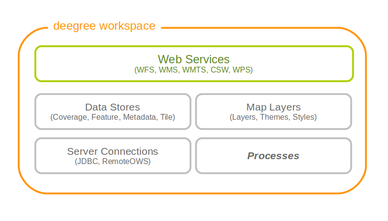
15.1. Java process provider
The Java process provider is a well-defined container for processes written in the Java programming language. In order to set up a working Java process provider resource, two things are required:
-
A Java process provider configuration file
-
A Processlet: Java class with the actual process code
The first item is an XML resource configuration file like any other deegree resource configuration. The second is special to this kind of resource. It provides the byte code with the process logic and has to be accessible by deegree’s classloader. There are several options to make custom Java code available to deegree webservices (see Java code and the classpath for details), but the most common options are:
-
Putting class files into the classes/ directory of the workspace
-
Putting JAR files into the modules/ directory of the workspace
15.1.1. Minimal configuration example
A very minimal valid configuration example looks like this:
Java process provider: Minimal example (resource configuration)
<ProcessDefinition configVersion="3.4.0" processVersion="1.0.0" xmlns="http://www.deegree.org/processes/java"
  xmlns:xsi="http://www.w3.org/2001/XMLSchema-instance" xsi:schemaLocation="http://www.deegree.org/processes/java http://schemas.deegree.org/processes/java/3.4.0/java.xsd">
  <Identifier>Process42</Identifier>
  <JavaClass>Processlet42</JavaClass>
  <Title>Calculates the answer to life, the universe and everything</Title>
  <OutputParameters>
    <LiteralOutput>
      <Identifier>Answer</Identifier>
      <Title>The universal answer</Title>
    </LiteralOutput>
  </OutputParameters>
</ProcessDefinition>
This example defines a bogus process with the following properties:
-
Identifier: Process42
-
Bound to Java code from class Processlet42
-
Title Calculates the answer to life, the universe and everything (returned in WPS responses)
-
No input parameters
-
Single output parameter with identifier Answer and title The universal answer
In order to make this configuration work, a matching Processlet class is required:
Java process provider: Minimal example (Java code)
import org.deegree.services.wps.Processlet;
import org.deegree.services.wps.ProcessletException;
import org.deegree.services.wps.ProcessletExecutionInfo;
import org.deegree.services.wps.ProcessletInputs;
import org.deegree.services.wps.ProcessletOutputs;
import org.deegree.services.wps.output.LiteralOutput;

public class Processlet42 implements Processlet {

    @Override
    public void process( ProcessletInputs in, ProcessletOutputs out, ProcessletExecutionInfo info )
                            throws ProcessletException {
        LiteralOutput output = (LiteralOutput) out.getParameter( "Answer" );
        output.setValue( "42" );
    }

    @Override
    public void init() {
        // nothing to initialize
    }

    @Override
    public void destroy() {
        // nothing to destroy
    }
}
15.1.2. More complex configuration example
A more complex configuration example looks like this:
Java process provider: More complex example (resource configuration)
<ProcessDefinition configVersion="3.4.0" processVersion="1.0.0" storeSupported="true" statusSupported="false"
  xmlns="http://www.deegree.org/processes/java" xmlns:xsi="http://www.w3.org/2001/XMLSchema-instance"
  xsi:schemaLocation="http://www.deegree.org/processes/java http://schemas.deegree.org/processes/java/3.4.0/java.xsd">
  <Identifier>Addition</Identifier>
  <JavaClass>AdditionProcesslet</JavaClass>
  <Title>Process for adding two integer values.</Title>
  <Abstract>The purpose of this process is to provide new users with a simple example process.</Abstract>
  <InputParameters>
    <LiteralInput>
      <Identifier>SummandA</Identifier>
      <Title>First summand </Title>
      <Abstract>This parameter specifies the first summand for a simple addition.</Abstract>
      <DataType reference="http://www.w3.org/TR/xmlschema-2/#integer">integer</DataType>
      <DefaultUOM>meters</DefaultUOM>
      <OtherUOM>centimeters</OtherUOM>
    </LiteralInput>
    <LiteralInput>
      <Identifier>SummandB</Identifier>
      <Title>Second summand </Title>
      <Abstract>This parameter specifies the second summand for a simple addition.</Abstract>
      <DataType reference="http://www.w3.org/TR/xmlschema-2/#integer">integer</DataType>
      <DefaultUOM>meters</DefaultUOM>
      <OtherUOM>centimeters</OtherUOM>
    </LiteralInput>
  </InputParameters>
  <OutputParameters>
    <LiteralOutput>
      <Identifier>Sum</Identifier>
      <Title>The result of the addition operation</Title>
      <DataType reference="http://www.w3.org/TR/xmlschema-2/#integer">integer</DataType>
      <DefaultUOM>meters</DefaultUOM>
      <OtherUOM>centimeters</OtherUOM>
    </LiteralOutput>
  </OutputParameters>
</ProcessDefinition>
This example defines a demonstration process with the following properties:
-
Identifier: AdditionProcess
-
Bound to Java code from class AdditionProcesslet
-
Title Process for adding two integer values. (returned in WPS responses)
-
Two integer input parameters SummandA and SummandB with title, abstract and unit of measure
-
Single integer output parameter with identifier Sum, title and unit of measure
In order to make this configuration work, a matching Processlet class is required:
Java process provider: Minimal example (Java code)
import org.deegree.services.wps.Processlet;
import org.deegree.services.wps.ProcessletException;
import org.deegree.services.wps.ProcessletExecutionInfo;
import org.deegree.services.wps.ProcessletInputs;
import org.deegree.services.wps.ProcessletOutputs;
import org.deegree.services.wps.input.LiteralInput;
import org.deegree.services.wps.output.LiteralOutput;

public class AdditionProcesslet implements Processlet {

    public void process( ProcessletInputs in, ProcessletOutputs out, ProcessletExecutionInfo info )
                            throws ProcessletException {
        int summandA = Integer.parseInt( ( (LiteralInput) in.getParameter( "SummandA" ) ).getValue() );
        int summandB = Integer.parseInt( ( (LiteralInput) in.getParameter( "SummandB" ) ).getValue() );
        int sum = summandA + summandB;

        LiteralOutput output = (LiteralOutput) out.getParameter( "Sum" );
        output.setValue( "" + sum );
    }

    public void destroy() {}

    public void init() {}
}
15.1.3. Configuration options
The configuration format for the Java process provider is defined by schema file http://schemas.deegree.org/processes/java/3.0.0/java.xsd. The following table lists all available configuration options. When specifiying them, their order must be respected.
| Option | Cardinality | Value | Description |
|---|---|---|---|
@processVersion |
1 |
String |
Release version of this process (metadata) |
@storeSupported |
0..1 |
Boolean |
If set to true, asynchronous execution will become available |
@statusSupported |
0..1 |
Boolean |
If set to true, process code provides status information |
Identifier |
1 |
String |
Identifier of the process |
JavaClass |
1 |
String |
Fully qualified name of a Processlet that implements the process logic |
Title |
1 |
String |
Short and meaningful title (metadata) |
Abstract |
0..1 |
String |
Short, human readable description (metadata) |
Metadata |
0..n |
String |
Additional metadata |
Profile |
0..n |
String |
Profile to which the WPS process complies (metadata) |
WSDL |
0..1 |
String |
URL of a WSDL document which describes this process (metadata) |
InputParameters |
0..1 |
Complex |
Definition and metadata of the input parameters |
OutputParameters |
1 |
Complex |
Definition and metadata of the output parameters |
The following sections describe these options and their sub-options in detail, as well as the Processlet API.
15.1.4. General options
All general options just provide metadata that the WPS reports to client. They don’t affect the behaviour of the configured process.
-
processVersion: The processVersion attribute has to be managed by the process developer and describes the version of the process implementation. This parameter is usually increased when changes to the implementation of a process apply.
-
Identifier: An unambiguous identifier
-
Title: Short and meaningful title
-
Abstract: Short, human readable description
-
Metadata: Additional metadata
-
Profile: Profile to which the WPS process complies
-
WSDL: URL of a WSDL document which describes this process
|
Note
|
These options directly relate to metadata defined in the WPS 1.0.0 specification. |
15.1.5. The Processlet API
Option JavaClass specifies the fully qualified name of a Java class that implement deegree’s Processlet Java interface. This interface is part of an API that hides the complexity of the WPS protocol while providing efficient and scalable handling of input and output parameters. By using this API, the process developer can focus on implementing the process logic without having to care of the details of the protocol:
-
Request encoding (KVP, XML, SOAP)
-
Input parameter passing variants (inline, by reference)
-
Output parameter representation (inline, by reference)
-
Storing of response documents
-
Synchronous/asynchronous execution
The interface looks like this:
Java process provider: Processlet interface
package org.deegree.services.wps;

public interface Processlet {

    /**
     * Called by the {@link ProcessManager} to perform an execution of this {@link Processlet}.
     * <p>
     * The typical workflow is:
     * <ol>
     * <li>Get inputs from <code>in</code> parameter</li>
     * <li>Parse inputs into the required format (e.g. GML)</li>
     * <li>Do computation.</li>
     * <li>Transform computational results into required format (e.g. GML)</li>
     * <li>Write results to <code>out</code> parameter</li>
     * </ol>
     *
     * @param in
     *            input arguments to be processed, never <code>null</code>
     * @param out
     *            used to store the process outputs, never <code>null</code>
     * @param info
     *            can be used to provide execution information, i.e. percentage completed and start/success messages
     *            that it wants to make known to clients, never <code>null</code>
     * @throws ProcessletException
     *             may be thrown by the processlet to indicate a processing exception
     */
    public void process( ProcessletInputs in, ProcessletOutputs out, ProcessletExecutionInfo info )
                            throws ProcessletException;

    /**
     * Called by the {@link ProcessManager} to indicate to a {@link Processlet} that it is being placed into service.
     */
    public void init();

    /**
     * Called by the {@link ProcessManager} to indicate to a {@link Processlet} that it is being taken out of service.
     * <p>
     * This method gives the {@link Processlet} an opportunity to clean up any resources that are being held (for
     * example, memory, file handles, threads) and make sure that any persistent state is synchronized with the
     * {@link Processlet}'s current state in memory.
     * </p>
     */
    public void destroy();
}
As you can see, the interface defines three methods:
-
init(): Called once when the workspace initializes the Java process provider resource that references the class.
-
destroy(): Called once when the workspace destroys the Java process provider resource that references the class.
-
process(…): Called every time an Execute request is sent to the WPS that targets this Processlet. The method usually reads the input parameters, performs the actual computation and writes the output parameters.
|
Note
|
The Processlet interface mimics the well-known Java Servlet interface (hence the name). A Servlet developer does not need to care of the details of HTTP. Similarly, a Processlet developer does not need to care of the details of the WPS protocol. |
|
Note
|
The Java process provider instantiates the Processlet class only once. However, multiple simultaneous executions of a Processlet are possible (in case parallel Execute-requests are sent to a WPS), and therefore, the Processlet code must be implemented in a thread-safe manner (just like Servlets). |
Processlet compilation
In order to succesfully compile a Processlet implementation, you will need to make the Processlet API available to the compiler. Generally, this means that the Java module deegree-services-wps (and it’s dependencies) have to be on the build path. We suggest to use Apache Maven for this. Here’s an example POM for your convenience:
Java process provider: Example Maven POM for compiling processlets
<project xmlns="http://maven.apache.org/POM/4.0.0" xmlns:xsi="http://www.w3.org/2001/XMLSchema-instance"
  xsi:schemaLocation="http://maven.apache.org/POM/4.0.0 http://maven.apache.org/maven-v4_0_0.xsd">
  <modelVersion>4.0.0</modelVersion>
  <artifactId>processlet-examples</artifactId>
  <packaging>jar</packaging>
  <name>processlet-examples</name>
  <description>Maven project for compiling Processlets</description>

  <parent>
    <groupId>org.deegree</groupId>
    <artifactId>deegree</artifactId>
    <version>3.4.18</version>
  </parent>

  <repositories>
    <repository>
      <id>deegree-repo</id>
      <url>https://repo.deegree.org/content/groups/public</url>
      <releases>
        <updatePolicy>never</updatePolicy>
      </releases>
      <snapshots>
        <enabled>true</enabled>
      </snapshots>
    </repository>
  </repositories>

  <dependencies>
    <dependency>
      <groupId>org.deegree</groupId>
      <artifactId>deegree-services-wps</artifactId>
      <version>3.4.18</version>
    </dependency>
  </dependencies>

</project>|
Tip
|
You can use this POM to compile the example Processlets above. Just create an empty directory somewhere and save the example POM as pom.xml. Place the Processlet Java files into subdirectory src/main/java/ (as files Processlet42.java / AdditionProcesslet.java). On the command line, change to the project directory and use mvn package (Apache Maven 3.0 and a compatible Java JDK have to be installed). Subdirectory target should now contain a JAR file that you can copy into the modules/ directory of the deegree workspace. |
Testing Processlets using raw WPS requests
|
Note
|
In order to perform WPS request to access your process provider/Processlet, you need to have an active Web Processing Service (WPS) resource in your workspace (which handles the WPS protocol and forwards the request to the process provider and the processlet). |
The general idea of the WPS specification is that a client connects to a WPS server and invokes processes offered by the server to perform a computation. However, in some cases, you may just want to send raw WPS requests to a server and check the response yourself (e.g. for testing the behaviour of your processlet). The WPS 1.0.0 specification defines KVP, XML and SOAP-encoded requests. All encodings are supported by the deegree WPS, so you can choose the most appropriate one for your use-case. For sending KVP-requests, you can simply use your web browser (or a command line tools like wget or curl). XML or SOAP requests can be send using deegree’s generic client.
Some KVP GetCapabilities/DescribeProcess request examples for checking the metadata of processes:
Some simple KVP Execute request examples for invoking processes:
|
Tip
|
The WPS 1.0.0 specification (and the deegree WPS) support many features with regard to process invocation, such as input parameter passing (inline or by reference), return parameters (inline or by reference), response variants and asynchronous execution. Example workspace 4: Web Processing Service demo contains XML example requests which demonstrate most of these features. |
15.1.6. Input and output parameters
Besides the process logic, the most crucial topic of WPS process implementation is the standard-compliant definition and handling of input and output parameters. The deegree WPS and the Java process provider support all parameter types that are defined by the WPS 1.0.0 specification:
-
LiteralInput/LiteralOutput: Literal values, e.g. "red", "42" or "highway 66"
-
BoundingBoxInput/BoundingBoxOutput: A geo-referenced bounding box
-
ComplexInput/ComplexOutput: Either an XML structure (e.g. GML encoded features) or binary data (e.g. coverage data as GeoTIFF)
In order to create your own process, first find out which input and output parameters you want it to have. During implementation, each parameter has to be considered twice:
-
It has to be defined in the resource configuration file
-
It has to be read or written in the Processlet
The definition in the resource configuration is mostly to specify metadata (identifier, title, abstract, datatype) of the parameter. The WPS will report it in response to DescribeProcess requests. When performing Execute requests, the deegree WPS will also perform a basic check of the validity of the input parameters (identifier, number of occurences, type) and respond with an ExceptionReport if the constraints are not met.
Basics of defining input and output parameters
In order to define a parameter of a process, create a new child element in your process provider configuration:
-
Input: Add a LiteralInput, BoundingBoxInput or ComplexInput element to section InputParameters
-
Output: Add a LiteralOutput, BoundingBoxOutput or ComplexOutput element to section OutputParameters
Here’s an InputParameters example that defines four parameters:
Java process provider: Example for InputParameters section
<InputParameters>
  <LiteralInput>
    <Identifier>LiteralInput</Identifier>
    <Title>Example literal input </Title>
    <Abstract>This parameter specifies how long the execution of the process takes (the process sleeps for this time).
      May be specified in seconds or minutes.</Abstract>
    <DataType reference="http://www.w3.org/TR/xmlschema-2/#integer">integer</DataType>
    <DefaultUOM>seconds</DefaultUOM>
    <OtherUOM>minutes</OtherUOM>
  </LiteralInput>
  <BoundingBoxInput>
    <Identifier>BBOXInput</Identifier>
    <Title>BBOXInput</Title>
    <DefaultCRS>EPSG:4326</DefaultCRS>
  </BoundingBoxInput>
  <ComplexInput>
    <Identifier>XMLInput</Identifier>
    <Title>XMLInput</Title>
    <DefaultFormat mimeType="text/xml" />
  </ComplexInput>
  <ComplexInput>
    <Identifier>BinaryInput</Identifier>
    <Title>BinaryInput</Title>
    <DefaultFormat mimeType="image/png" encoding="base64" />
  </ComplexInput>
</InputParameters>
Here’s an OutputParameters example that defines four parameters:
Java process provider: Example for OutputParameters section
<OutputParameters>
<LiteralOutput>
<Identifier>LiteralOutput</Identifier>
<Title>A literal output parameter</Title>
<DataType reference="http://www.w3.org/TR/xmlschema-2/#integer">integer</DataType>
<DefaultUOM>seconds</DefaultUOM>
</LiteralOutput>
<BoundingBoxOutput>
<Identifier>BBOXOutput</Identifier>
<Title>A bounding box output parameter</Title>
<DefaultCRS>EPSG:4326</DefaultCRS>
</BoundingBoxOutput>
<ComplexOutput>
<Identifier>XMLOutput</Identifier>
<Title>An XML output parameter</Title>
<DefaultFormat mimeType="text/xml" />
</ComplexOutput>
<ComplexOutput>
<Identifier>BinaryOutput</Identifier>
<Title>A binary output parameter</Title>
<DefaultFormat mimeType="image/png" encoding="base64" />
</ComplexOutput>
</OutputParameters>Each parameter definition element has the following common options:
| Option | Cardinality | Value | Description |
|---|---|---|---|
Identifier |
1 |
String |
Identifier of the parameter |
Title |
1 |
String |
Short and meaningful title (metadata) |
Abstract |
0..1 |
String |
Short, human readable description (metadata) |
Metadata |
0..n |
String |
Additional metadata |
Besides the identifier of the parameter, these parameters just define metadata that the WPS reports. Additionally, each input parameter definition element supports the following two attributes:
| Option | Cardinality | Value | Description |
|---|---|---|---|
@minOccurs |
0..n |
Integer |
Minimum number of times the input has to be present in a request, default: 1 |
@maxOccurs |
0..n |
String |
Maximum number of times the input has to be present in a request, default: 1 |
The differences and special options of the individual parameter types (Literal, Bounding Box, Complex) are described in the following sections.
Basics of accessing input and output parameters
The first two arguments of Processlet#process(..) provide access to the input parameter values and output parameter sinks. The first argument is of type ProcessletInputs and encapsulates the process input parameters. Here’s an example snippet that shows how to access the input parameter with identifier LiteralInput:
public void process( ProcessletInputs in, ProcessletOutputs out, ProcessletExecutionInfo info )
throws ProcessletException {
ProcessletInput literalInput = in.getParameter( "LiteralInput" );
[...]
}The getParameter(…) method of ProcessletInputs takes the identifier of the process parameter as an argument and returns a ProcessletInput (without the s) object that provides access to the actual value of the process parameter. Here’s the ProcessletInput interface:
public interface ProcessletInput {
/**
* Returns the identifier or name of the input parameter as defined in the process description.
*
* @return the identifier of the input parameter
*/
public CodeType getIdentifier();
/**
* Returns the title that has been supplied with the input parameter, normally available for display to a human.
*
* @return the title provided with the input, may be null
*/
public LanguageString getTitle();
/**
* Returns the narrative description that has been supplied with the input parameter, normally available for display
* to a human.
*
* @return the abstract provided with the input, may be null
*/
public LanguageString getAbstract();
}This interface does not provide access to the passed value, but ProcessletInput is the parent of three Java types that directly correspond to three input parameter types of the process provider configuration:
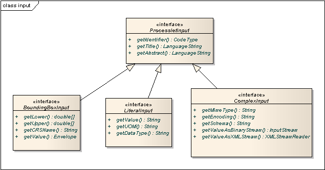
For example, if your input parameter definition "A" is a BoundingBoxInput, then the Java type for this parameter will be BoundingBoxInput as well. In your Java code, use a type cast to narrow the return type (and gain access to the passed value):
public void process( ProcessletInputs in, ProcessletOutputs out, ProcessletExecutionInfo info )
throws ProcessletException {
BoundingBoxInput inputA = (BoundingBoxInput) in.getParameter( "A" );
[...]
}|
Tip
|
If an input parameter can occur multiple times (maxOccurs > 1 in the definition), use method getParameters(…) instead of getParameter(…). The latter method returns a List of ProcessletInput objects. |
Output parameters are treated in a similar manner. The second parameter of Processlet#process(..) provides to output parameter sinks. It is of type ProcessletOutputs. Here’s a basic usage example:
public void process( ProcessletInputs in, ProcessletOutputs out, ProcessletExecutionInfo info )
throws ProcessletException {
ProcessletOutput literalOutput = out.getParameter( "LiteralOutput" );
[...]
}Here’s the ProcessletOutput interface:
public interface ProcessletOutput {
/**
* Returns the identifier or name of the output parameter as defined in the process description.
*
* @return the identifier of the output parameter
*/
public CodeType getIdentifier();
/**
* Returns the title that has been supplied with the request of the output parameter, normally available for display
* to a human.
*
* @return the title provided with the output, may be null
*/
public LanguageString getSubmittedTitle();
/**
* Returns the narrative description that has been supplied with the request of the output parameter, normally
* available for display to a human.
*
* @return the abstract provided with the output, may be null
*/
public LanguageString getSubmittedAbstract();
/**
* Returns whether this output parameter has been requested by the client, i.e. if it will be present in the result.
* <p>
* NOTE: If the parameter is requested, the {@link Processlet} must set a value for this parameter, if not, it may
* or may not do so. However, for complex output parameters that are not requested, it is advised to omit them for
* more efficient execution of the {@link Processlet}.
* </p>
*
* @return true, if the {@link Processlet} must set the value of this parameter (in this execution), false otherwise
*/
public boolean isRequested();
/**
* Sets the parameter title in the response sent to the client.
*
* @param title
* the parameter title in the response sent to the client
*/
public void setTitle( LanguageString title );
/**
* Sets the parameter abstract in the response sent to the client.
*
* @param summary
* the parameter abstract in the response sent to the client
*/
public void setAbstract( LanguageString summary );
}Again, there are three subtypes. Each subtype of ProcessletOutput corresponds to one output parameter type:
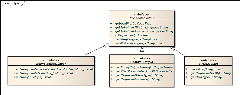
Literal parameters
Literal input and output parameter definitions have the following additional options:
| Option | Cardinality | Value | Description |
|---|---|---|---|
DataType |
0..1 |
String |
Data Type of this input (or output), default: unspecified (string) |
DefaultUOM |
0..1 |
String |
Default unit of measure, default: unspecified |
OtherUOM |
0..n |
String |
Alternative unit of measure |
DefaultValue |
0..1 |
String |
Default value of this input (only for inputs) |
AllowedValues |
0..1 |
Complex |
Constraints based on value sets and ranges (only for inputs) |
ValidValueReference |
0..1 |
Complex |
References to externally defined value sets and ranges (only for inputs) |
These options basically define metadata that the WPS publishes to clients. For the sub-options of the AllowedValues and ValidValueReference options, please refer to the WPS 1.0.0 specification or the XML schema for the Java process provider configuration format (http://schemas.deegree.org/processes/java/3.0.0/java.xsd).
In order to work with a LiteralInput parameter in the Processlet code, the corresponding Java type offers the following methods:
/**
* Returns the literal value.
*
* @see #getUOM()
* @return the literal value (has to be in the correct UOM)
*/
public String getValue();
/**
* Returns the UOM (unit-of-measure) for the literal value, it is guaranteed that the returned UOM is supported for
* this parameter (according to the process description).
*
* @return the requested UOM (unit-of-measure) for the literal value, may be null if no UOM is specified in the
* process description
*/
public String getUOM();
/**
* Returns the (human-readable) literal data type from the process definition, e.g. <code>integer</code>,
* <code>real</code>, etc).
*
* @return the data type, or null if not specified in the process definition
*/
public String getDataType();Similarly, the LiteralOutput type offers the following methods:
/**
* Sets the value for this output parameter of the {@link Processlet} execution.
*
* @see #getRequestedUOM()
* @param value
* value to be set (in the requested UOM)
*/
public void setValue( String value );
/**
* Returns the requested UOM (unit-of-measure) for the literal value, it is guaranteed that this UOM is supported
* for this parameter (according to the process description).
*
* @return the requested UOM (unit-of-measure) for the literal value, may be null
*/
public String getRequestedUOM();
/**
* Returns the announced literal data type from the process definition (e.g. integer, real, etc) as an URI, such as
* <code>http://www.w3.org/TR/xmlschema-2/#integer</code>.
*
* @return the data type, or null if not specified in the process definition
*/
public String getDataType();BoundingBox parameters
BoundingBox input and output parameter definitions have the following additional options:
| Option | Cardinality | Value | Description |
|---|---|---|---|
DefaultCRS |
1 |
String |
Identifier of the default coordinate reference system |
OtherCRS |
0..n |
String |
Additionally supported coordinate reference system |
In order to work with a BoundingBoxInput parameter in the Processlet code, the corresponding Java type offers the following methods:
/**
* Returns the lower corner point of the bounding box.
*
* @return the lower corner point
*/
public double[] getLower();
/**
* Returns the upper corner point of the bounding box.
*
* @return the upper corner point
*/
public double[] getUpper();
/**
* Returns the CRS (coordinate reference system) name of the bounding box.
*
* @return the CRS (coordinate reference system) name or null if unspecified
*/
public String getCRSName();
/**
* Returns the bounding box value, it is guaranteed that the CRS (coordinate reference system) of the returned
* {@link Envelope} is supported for this parameter (according to the process description).
*
* @return the value
*/
public Envelope getValue();Similarly, the BoundingBoxOutput type offers the following methods:
/**
* Sets the value for this output parameter of the {@link Processlet} execution.
*
* @param lowerX
* @param lowerY
* @param upperX
* @param upperY
* @param crsName
*/
public void setValue( double lowerX, double lowerY, double upperX, double upperY, String crsName );
/**
* Sets the value for this output parameter of the {@link Processlet} execution.
*
* @param lower
* @param upper
* @param crsName
*/
public void setValue( double[] lower, double[] upper, String crsName );
/**
* Sets the value for this output parameter of the {@link Processlet} execution.
*
* @param value
* value to be set
*/
public void setValue( Envelope value );Complex parameters
Complex input and output parameter definitions have the following additional options:
| Option | Cardinality | Value | Description |
|---|---|---|---|
@maximumMegabytes |
0..n |
Integer |
Maximum file size, in megabytes (only for inputs) |
DefaultFormat |
1 |
Complex |
Definition of the default XML or binary format |
OtherFormats |
0..n |
Complex |
Definition of an alternative XML or binary format |
A complex format (DefaultFormat/OtherFormat) is defined via three attributes (compare with the WPS 1.0.0 specification):
| Option | Cardinality | Value | Description |
|---|---|---|---|
@mimeType |
0..1 |
String |
Mime type of the content, default: unspecified |
@encoding |
0..1 |
String |
Encoding of the content, default: unspecified |
@schema |
0..1 |
String |
XML schema of the content, default: unspecified |
In order to work with a ComplexInput parameter in the Processlet code, the corresponding Java type offers the following methods:
/**
* Returns the mime type of the input.
*
* @return the mime type of the input, may be <code>null</code>
*/
public String getMimeType();
/**
* Returns the encoding information supplied with the input.
*
* @return the encoding information supplied with the input, may be <code>null</code>
*/
public String getEncoding();
/**
* Returns the schema URL supplied with the input.
*
* @return the schema URL supplied with the input, may be <code>null</code>
*/
public String getSchema();
/**
* Returns an {@link InputStream} for accessing the complex value as a raw stream of bytes (usually for binary
* input).
* <p>
* NOTE: Never use this method if the input parameter is encoded in XML -- use {@link #getValueAsXMLStream()}
* instead. Otherwise erroneous behaviour has to be expected (if the input value is given embedded in the execute
* request document).
* </p>
*
* @see #getValueAsXMLStream()
* @return the input value as a raw stream of bytes
* @throws IOException
* if accessing the value fails
*/
public InputStream getValueAsBinaryStream()
throws IOException;
/**
* Returns an {@link XMLStreamReader} for accessing the complex value as an XML event stream.
* <p>
* NOTE: Never use this method if the input parameter is a binary value -- use {@link #getValueAsBinaryStream()}
* instead.
* </p>
* The returned stream will point at the first START_ELEMENT event of the data.
*
* @return the input value as an XML event stream, current event is START_ELEMENT (the root element of the data
* object)
* @throws IOException
* if accessing the value fails
* @throws XMLStreamException
*/
public XMLStreamReader getValueAsXMLStream()
throws IOException, XMLStreamException;Similarly, the ComplexOutput type offers the following methods:
/**
* Returns a stream for writing binary output.
*
* @return stream for writing binary output, never <code>null</code>
*/
public OutputStream getBinaryOutputStream();
/**
* Returns a stream for for writing XML output. The stream is already initialized with a
* {@link XMLStreamWriter#writeStartDocument()}.
*
* @return a stream for writing XML output, never <code>null</code>
* @throws XMLStreamException
*/
public XMLStreamWriter getXMLStreamWriter()
throws XMLStreamException;
/**
* Returns the requested mime type for the complex value, it is guaranteed that the mime type is supported for this
* parameter (according to the process description).
*
* @return the requested mime type, never <code>null</code> (as each complex output format has a default mime type)
*/
public String getRequestedMimeType();
/**
* Returns the requested XML format for the complex value (specified by a schema URL), it is guaranteed that the
* format is supported for this parameter (according to the process description).
*
* @return the requested schema (XML format), may be <code>null</code> (as a complex output format may omit schema
* information)
*/
public String getRequestedSchema();
/**
* Returns the requested encoding for the complex value, it is guaranteed that the encoding is supported for this
* parameter (according to the process description).
*
* @return the requested encoding, may be <code>null</code> (as a complex output format may omit encoding
* information)
*/
public String getRequestedEncoding();15.1.7. Asynchronous execution and status information
The WPS protocol offers support for asynchronous execution of processes as well as providing status information for long running processes. The following two options of the Java process provider deal with this:
-
@storeSupported: If the storeSupported attribute is set to true, asynchronous execution of the process will be possible. A WPS client can then choose between synchronous execution (default) and asynchronous execution. Note that this doesn’t add any requirements to the implementation of the Processlet code, this is taken care of automatically by the deegree WPS.
-
@statusSupported: If statusSupported is set to true, the WPS will announce that the process can provide status information, i.e. execution percentage. In order for this to work, the Processlet code has to provide status information.
Providing status information in the Processlet code
The third parameter that’s passed to the execute(…) method is of type ProcessletExecutionInfo. This type provides the following methods:
/**
* Allows the {@link Processlet} to indicate the percentage of the process that has been completed, where 0 means
* the process has just started, and 99 means the process is almost complete. This value is expected to be accurate
* to within ten percent.
*
* @param percentCompleted
* the percentage value to be set, a number between 0 and 99
*/
public void setPercentCompleted( int percentCompleted );
/**
* Allows the {@link Processlet} to provide a custom started message for the client.
*
* @param message
*/
public void setStartedMessage( String message );
/**
* Allows the {@link Processlet} to provide a custom finished message for the client.
*
* @param message
*/
public void setSucceededMessage( String message );|
Tip
|
Depending on the type of computation that a Processlet performs, it may or may not be trivial to provide correct progress information via setPercentCompleted(…). |
16. Coordinate reference systems
Coordinate reference system identifiers are used in many places in deegree webservices:
-
In incoming service requests (e.g. GetFeature-requests to the WFS)
-
In a lot of resource configuration files (e.g. in Feature stores)
deegree has an internal CRS database that contains many commonly used coordinate reference systems. Some examples for valid CRS identifiers:
-
EPSG:4258
-
urn:ogc:def:crs:epsg::4258
-
urn:opengis:def:crs:epsg::4258
|
Tip
|
As a rule of thumb, deegree’s CRS database uses the EPSG:12345 identifier variant to indicate XY axis order, while the URN variants (such as urn:ogc:def:crs:epsg::12345) always use the official axis order defined by the EPSG. For example EPSG:4258 and urn:ogc:def:crs:epsg::4258 both refer to ETRS89, but EPSG:4258 means ETRS89 in XY-order, while urn:ogc:def:crs:epsg::4258 is YX (the official order defined by the EPSG for this CRS). |
|
Note
|
The CRS subsystem is not fully integrated with the deegree workspace yet. Rework and proper documentation are on the roadmap for one of the next releases. If you have trouble finding a specific CRS, please contact the deegree mailing lists for support. |
17. deegree REST interface
deegree offers a REST like web interface to access and configure the deegree workspace. You can use it to alter configuration, restart workspaces or resources and start a different workspace.
17.1. Setting up the interface
The servlet that handles the REST interface is already running if you use the standard web.xml deployment descriptor. For security reasons the REST API is only accessible after successful authentication against the servlet container. When using Apache Tomcat you’ll need to add a user with the role deegree to your Tomcat configuration conf/tomcat-users.xml file.
Once you did that, you can get an overview of available 'commands' by requesting http://localhost:8080/deegree-webservices/config. You’ll need to provide the username/password credentials you configured for every request within the HTTP header (HTTP BASIC authentication).
Here’s an example output:
No action specified. Available actions: GET /config/download[/path] - download currently running workspace or file in workspace GET /config/download/wsname[/path] - download workspace with name <wsname> or file in workspace GET /config/restart - restart currently running workspace GET /config/restart[/path] - restarts all resources connected to the specified one GET /config/restart/wsname - restart with workspace <wsname> GET /config/update - update currently running workspace, rescan config files and update resources GET /config/update/wsname - update with workspace <wsname>, rescan config files and update resources GET /config/listworkspaces - list available workspace names GET /config/list[/path] - list currently running workspace or directory in workspace GET /config/list/wsname[/path] - list workspace with name <wsname> or directory in workspace GET /config/invalidate/datasources/tile/id/matrixset[?bbox=] - invalidate part or all of a tile store cache's tile matrix set GET /config/crs/list - list available CRS definitions POST /config/crs/getcodes with wkt=<wkt> - retrieves a list of CRS codes corresponding to the WKT (POSTed KVP) GET /config/crs/<code> - checks if a CRS definition is available, returns true/false PUT /config/upload/wsname.zip - upload workspace <wsname> PUT /config/upload/path/file - upload file into current workspace PUT /config/upload/wsname/path/file - upload file into workspace with name <wsname> DELETE /config/delete[/path] - delete currently running workspace or file in workspace DELETE /config/delete/wsname[/path] - delete workspace with name <wsname> or file in workspace HTTP response codes used: 200 - ok 403 - if you tried something you shouldn't have 404 - if a file or directory needed to fulfill a request was not found 500 - if something seriously went wrong on the server side
17.2. Detailed explanation
Let’s see how the commands work in detail. In general, you can specify a path relative to the workspace almost anywhere. With no path given, you act on the workspace, with a path given, you act on that part of the workspace.
17.2.1. Downloading
In order to download the complete workspace, you request http://localhost:8080/deegree-webservices/config/download. Since the workspace is made up of many files, you get a .zip file. If you just want to download the featurestore configuration named inspire, you request http://localhost:8080/deegree-webservices/config/download/datasources/feature/inspire.xml.
To use a different workspace instead of the currently running one, use http://localhost:8080/deegree-webservices/config/download/otherworkspace (you may also specify a file within that workspace).
17.2.2. Restarting
You can restart the currently running workspace using http://localhost:8080/deegree-webservices/config/restart, or start another workspace using http://localhost:8080/deegree-webservices/config/restart/anotherworkspace. To restart all resources connected a specific one use eg. http://localhost:8080/deegree-webservices/config/restart/datasources/feature/inspire.
17.2.3. Updating
You can update the currently running workspace using
http://localhost:8080/deegree-webservices/config/update,
or by name http://localhost:8080/deegree-webservices/config/update/thisworkspace.
Updating a workspace means that all resource changed since the last update or restart are restarted.
17.2.4. Listing
You can see what workspaces are available to the deegree installation by running http://localhost:8080/deegree-webservices/config/listworkspaces.
You can also browse through a workspace’s files by requesting eg. http://localhost:8080/deegree-webservices/config/list/datasources/, or to see the files in a workspace other than the one currently running http://localhost:8080/deegree-webservices/config/list/someworkspace/services/.
17.2.5. Storing
You can update or add files in a workspace, or upload a completely new workspace by sending a HTTP PUT request.
To upload a new workspace, send a .zip file with the workspace contents to http://localhost:8080/deegree-webservices/config/upload/someworkspace.zip. This will extract the workspace as someworkspace. Note that there should not be a parent directory in the .zip, it should contain folders like datasources or service directly.
To upload individual files send requests against http://localhost:8080/deegree-webservices/config/upload/path/to/file.xml, or with a workspace name prefix as usual (http://localhost:8080/deegree-webservices/config/upload/someworkspace/and/the/path/file.xml).
17.2.6. Deleting
Deletion works just like storing, except you send HTTP DELETE requests and instead of the upload path component you use delete. You can also delete whole directories with content by specifying just the path to the directory. Deleting workspaces is also possible, just specify the workspace name (without a .zip suffix).
17.2.7. Invalidating tile store caches
This is a special operation only possible for CachingTileStore resources. You can invalidate the whole cache, or just a part of it by requesting http://localhost:8080/deegree-webservices/config/invalidate/datasources/tile/configname/matrixsetname. You can specify a bounding box by appending it in the form ?bbox=minx,miny,maxx,maxy (just like in WMS requests).
17.2.8. CRS queries
You can get a list of all available CRS definitions by requesting http://localhost:8080/deegree-webservices/config/crs/list. Check if a specific CRS is configured in deegree by requesting http://localhost:8080/deegree-webservices/config/crs/EPSG:12345. The response will be the text true or false, depending whether the CRS is defined or not. If you have a WKT CRS definition, you can POST against http://localhost:8080/deegree-webservices/config/crs/getcodes to get a list of corresponding identifiers (experimental). Use the wkt parameter when posting to send the WKT definition.
18. Java modules and libraries
deegree webservices is a Java web application and based on code written in the Java programming language. As a user, you usually don’t need to care about this, unless you want to extend the default functionality available in a deegree webservices setup. This chapter provides some basic knowledge of JAR (Java archive) files, the Java classpath and describes how deegree webservices finds JARs. Additionally, it provides precise instructions for adding JARs so your deegree webservices instance can connect to Oracle Spatial and Microsoft SQL Server databases.
|
Note
|
The terms JAR, module and library are used interchangeably in this chapter. |
18.1. Java code and the classpath
Java code is usually packaged in JAR files. If you want to extend deegree’s codebase, you will have to add one or more JAR files to the so-called classpath[9]. Basically, there are two different types of classpaths that determine which JAR files are available to deegree webservices:
-
The web application classpath
-
The workspace classpath
The full classpath used by deegree webservices consists of the web application classpath and the workspace classpath. If conflicting files exist on both classpaths, the file on the workspace classpath takes precedence.
|
Tip
|
If you’re not familiar with classpath concepts and don’t have any special requirements, simply add your JAR files to the workspace classpath and ignore the web application classpath. |
18.1.1. Web application classpath
As deegree webservices is a Java web application, standard paths apply:
-
Directory WEB-INF/lib of the deegree web application (for JARs)
-
Directory WEB-INF/classes of the deegree web application (for Java class files)
-
Global directories for all web applications running in the container (depends on the actual web container)
When you add files to the web application claspath, you have to restart the web application or the web application container to make the new code available to deegree webservices.
|
Note
|
All Java libraries shipped with deegree webservices are located in the WEB-INF/lib directory of the deegree webservices webapp. If you downloaded the ZIP version, this directory is located in webapps/ROOT/WEB-INF/lib. |
18.1.2. Workspace classpath
When deegree webservices initializes the workspace, it scans directory modules/ of the active deegree workspace for files ending with .jar and adds them to the classpath. This can be very handy, as it allows to create self-contained workspaces (no fiddling with other directories required) and also has the benefit the you can reload the deegree workspace only after adding your libraries (instead of restarting the deegree webapp or the whole web application container).
|
Note
|
In addition to workspace directory modules/, directory classes/ can be used to add individual Java classes (and other files) to the classpath. This is usually not required. |
|
Warning
|
Since deegree 3.4 jdbc drivers are not longer loaded from workspace classpath. Instead deegree follows the commonly used method to only use jdbc drivers which are available either by the system (shared or server libraries) or by the application (WEB-INF/lib). |
18.2. Checking available JARs
In order to see which JARs are available to your deegree webservices instance/workspace, use the "module info" link in the general section of the service console:
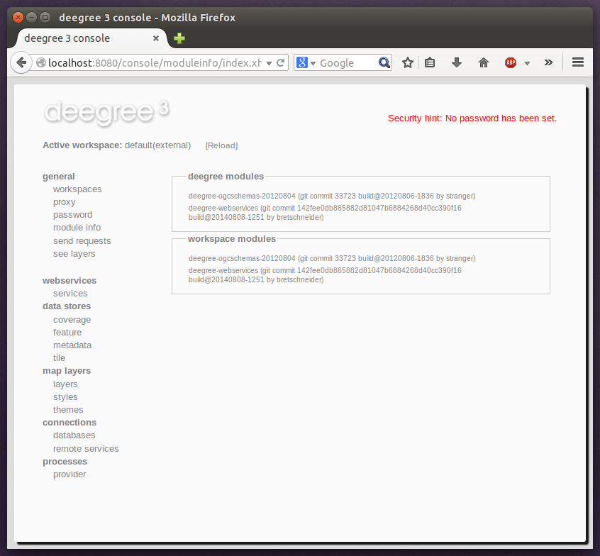
The list of JARs section displays the JARs found on the web application classpath, while the lower section displays the JARs found on the workspace classpath.
18.3. Adding database modules
By default, deegree webservices includes everything that is needed for connecting to PostgreSQL/PostGIS and Derby databases. If you want to connect to an Oracle Spatial or Microsoft SQL Server instance, you need to add additional Java libraries manually, as the required JDBC libraries are not included in the deegree webservices download (for license reasons).
18.3.1. Adding Oracle support
The following deegree resources support Oracle Spatial databases:
-
SimpleSQLFeatureStore
-
SQLFeatureStore
-
ISOMetadataStore
In order to enable Oracle connectivity for these resources, you need to add two JAR files (see Java code and the classpath):
18.3.2. Adding Oracle GeoRaster support
The OracleGeoraster coverage store supports GeoRaster Objects stored in Oracle databases.
In order to enable Oracle connectivity for these resources, you need to add the following JAR files (see Java code and the classpath):
|
Note
|
The Oracle Spatial and GeoRaster libraries can be found, without version number in filename, inside the Oracle Database installation directory. The sdo* files can be found at ORACLE_HOME/md/jlib, xdb6.jar at ORACLE_HOME/rdbms/jlib and xmlparserv2_sans_jaxp_services or xmlparserv2 at ORACLE_HOME/xdk/lib. |
|
Note
|
The xmlparserv2_sans_jaxp_services is the recommended library, as it does not contain META-INF/services/ entries. But if this library is not available the xmlparserv2 can be used instead. (In rare conditions this could set the oracle library as default XML parser, which could lead to unexpected behavior). |
18.3.3. Adding Microsoft SQL server support
The following deegree resources support Microsoft SQL Server:
-
SimpleSQLFeatureStore
-
SQLFeatureStore
-
ISOMetadataStore
In order to enable Microsoft SQL Server connectivity for these resources, you need to add two JAR files (see Java code and the classpath):
19. GDAL components
The GDAL library (http://www.gdal.org/) provides very comprehensive support for all kinds of geospatial raster formats. Any of these raster formats can be used to create Map layers for a deegree workspace by using either the GDAL Layer or the GDAL Tile Store.
|
Note
|
If there are alternative options for plugging your raster files into the deegree workspace (e.g. by using the GeoTIFFTileStore for GeoTIFF files), you may want to consider them first. As the GDAL library is not written in Java, it is required to install and connect additional (non-deegree) components in order to use it. Additionally, some technical considerations about GDAL dataset pooling and GDAL memory settings may be necessary to achieve optimal performance. |
19.1. Connecting GDAL and deegree
Before you can set up GDAL-based resources, the native GDAL library has to be installed correctly and must be accessible by your deegree webservices installation. Please see http://www.gdal.org/ for general GDAL installation instructions.
|
Note
|
Currently, GDAL library version 2.4 is supported. Other versions may work as well, but have not been tested. |
In order to verify that deegree webservices can use the GDAL library, check the log file of the web container (e.g. catalina.out for Tomcat). If you didn’t configure a GDAL settings file in your workspace yet, you should be able to locate the following lines upon workspace startup:
[13:06:40] INFO: [GdalSettings] --------------------------------------------------------------------------------
[13:06:40] INFO: [GdalSettings] GDAL JNI adapter.
[13:06:40] INFO: [GdalSettings] --------------------------------------------------------------------------------
[13:06:40] INFO: [GdalSettings] No gdal.xml in workspace. Not initializing GDAL JNI adapter.If a valid GDAL settings file is present in the active deegree workspace, the corresponding lines should look similar to this:
[13:16:54] INFO: [GdalSettings] --------------------------------------------------------------------------------
[13:16:54] INFO: [GdalSettings] GDAL JNI adapter.
[13:16:54] INFO: [GdalSettings] --------------------------------------------------------------------------------
[13:16:54] INFO: [GdalSettings] Using 'gdal.xml' from workspace for GDAL settings.
[13:16:54] INFO: [GdalSettings] Max number of open GDAL datasets: 5
[13:16:54] INFO: [GdalSettings] GDAL initialized successfully.In case a the GDAL settings file is present, but the GDAL library cannot be accessed, you will see something like the following:
[13:11:08] INFO: [GdalSettings] --------------------------------------------------------------------------------
[13:11:08] INFO: [GdalSettings] GDAL JNI adapter.
[13:11:08] INFO: [GdalSettings] --------------------------------------------------------------------------------
[13:11:08] INFO: [GdalSettings] Using 'gdal.xml' from workspace for GDAL settings.
Native library load failed.
java.lang.UnsatisfiedLinkError: no gdaljni in java.library.path
[13:11:08] ERROR: [JsfUtils] Workspace startup failed: org.gdal.gdal.gdalJNI.AllRegister()V(class java.lang.UnsatisfiedLinkError)
java.lang.UnsatisfiedLinkError: org.gdal.gdal.gdalJNI.AllRegister()V
at org.gdal.gdal.gdalJNI.AllRegister(Native Method)
at org.gdal.gdal.gdal.AllRegister(gdal.java:499)
at org.deegree.commons.gdal.GdalSettings.registerOnceQuietly(GdalSettings.java:113)
at org.deegree.commons.gdal.GdalSettings.registerGdal(GdalSettings.java:97)
at org.deegree.commons.gdal.GdalSettings.init(GdalSettings.java:92)
[...]In this case, ensure that the GDAL library is installed on your system and available via the dynamic library path used by the Java VM. You may need to adapt environment variables (e.g. LD_LIBRARY_PATH on Linux) to achieve this.
19.2. GDAL settings
The GDAL settings file gdal.xml belongs in the main directory of the deegree workspace.
19.2.1. Minimal GDAL settings example
The only mandatory element is OpenDatasets. A minimal valid configuration example looks like this:
GDAL settings (minimal example)
<GDALSettings configVersion="3.4.0"
xmlns="http://www.deegree.org/gdal" xmlns:xsi="http://www.w3.org/2001/XMLSchema-instance"
xsi:schemaLocation="http://www.deegree.org/gdal http://schemas.deegree.org/commons/gdal/3.4.0/gdal.xsd">
<OpenDatasets>5</OpenDatasets>
</GDALSettings>This configuration will register the GDAL JNI adapter and will allow a maximum of five GDAL datasets to be kept open for simultaneous access.
19.2.2. More complex GDAL settings example
GDAL settings (more complex example)
<GDALSettings configVersion="3.4.0"
xmlns="http://www.deegree.org/gdal" xmlns:xsi="http://www.w3.org/2001/XMLSchema-instance"
xsi:schemaLocation="http://www.deegree.org/gdal http://schemas.deegree.org/commons/gdal/3.4.0/gdal.xsd" />
<OpenDatasets>10</OpenDatasets>
<GDALOption name="GDAL_CACHEMAX">1000</GDALOption>
<GDALOption name="ECW_CACHE_MAXMEM">419430400</GDALOption>
</GDALSettings>This configuration will register the GDAL JNI adapter with the following settings:
-
A maximum of ten GDAL datasets will be kept open for simultaneous access
-
GDAL option GDAL_CACHEMAX is set to 1000
-
GDAL option ECW_CACHE_MAXMEM is set to 419430400
|
Note
|
A list of general GDAL parameters is available at http://trac.osgeo.org/gdal/wiki/ConfigOptions. Some parameters (such as ECW_CACHE_MAXMEM) are format specific and outlined on the respective pages in the GDAL documentation. |
19.2.3. Configuration options
The configuration format for the GDAL settings file is defined by schema file http://schemas.deegree.org/commons/gdal/3.4.0/gdal.xsd. The following table lists the two available configuration options. When specifiying them, their order must be respected.
| Option | Cardinality | Value | Description |
|---|---|---|---|
OpenDatasets |
1..1 |
Integer |
Number of open datasets / simultaneous file accesses |
GDALOption |
0..n |
String |
Name / value of parameter to pass on to the GDAL library |
19.3. GDAL Layer
A GDAL Layer is a map layer that is backed by one or more raster files. The native GDAL library is used to determine some metadata (e.g. bounding box) and to access the actual raster data.
|
Note
|
You may want to refer to the Map layers chapter for general information on using and defining layer resources. |
19.3.1. Configuration example
The only custom element in a GDAL Layer definition is File. A valid example looks like this:
GDAL Layers (example)
<GDALLayers configVersion="3.4.0"
xmlns="http://www.deegree.org/layers/gdal" xmlns:d="http://www.deegree.org/metadata/description"
xmlns:l="http://www.deegree.org/layers/base" xmlns:s="http://www.deegree.org/metadata/spatial">
<GDALLayer>
<l:Name>luchtfoto_2010</l:Name>
<d:Title>Orthophoto layer served from an ECW file</d:Title>
<s:CRS>EPSG:28992 EPSG:25831</s:CRS>
<l:ScaleDenominators min="0" max="10000" />
<File>/geodata/ecw/2010/Luchtfoto2010_25cm.ecw</File>
</GDALLayer>
</GDALLayers>This configuration will create a single layer resource with the following settings:
-
The file defines a single layer only
-
Name of the layer is luchtfoto_2010
-
Layer is offered in coordinate reference systems EPSG:28992 and EPSG:25831
-
File /geodata/ecw/2010/Luchtfoto2010_25cm.ecw will be accessed via GDAL to retrieve metadata and raster data
19.4. GDAL Tile Store
A GDAL tile store defines one or more tile data sets. Each of these tile data sets is based on a single raster file which is accessed using the native GDAL library.
|
Note
|
You may want to refer to the Tile stores chapter for general information on using and defining tile store resources. |
19.4.1. Minimal configuration example
A minimal valid configuration example looks like this:
GDAL Tile Store: Minimal configuration
<GDALTileStore configVersion="3.4.0"
xmlns="http://www.deegree.org/datasource/tile/gdal" xmlns:xsi="http://www.w3.org/2001/XMLSchema-instance"
xsi:schemaLocation="http://www.deegree.org/datasource/tile/gdal http://schemas.deegree.org/datasource/tile/gdal/3.4.0/gdal.xsd">
<TileDataSet>
<TileMatrixSetId>utah</TileMatrixSetId>
<File>../../data/test.tif</File>
</TileDataSet>
</GDALTileStore>This configuration will create a GDAL tile store resource with the following settings:
-
Tile store defines a single tile data set
-
Name of the tile data set is test (derived from file name)
-
Tile matrix set is utah
-
File ../../data/test.tif will be accessed via GDAL to retrieve the raster data
-
Output tile format is not set, defaults to image/png
19.4.2. More complex configuration example
A more complex example that uses all available configuration options:
GDAL Tile Store: More complex configuration
<GDALTileStore configVersion="3.4.0"
xmlns="http://www.deegree.org/datasource/tile/gdal" xmlns:xsi="http://www.w3.org/2001/XMLSchema-instance"
xsi:schemaLocation="http://www.deegree.org/datasource/tile/gdal http://schemas.deegree.org/datasource/tile/gdal/3.4.0/gdal.xsd">
<TileDataSet>
<Identifier>2010</Identifier>
<TileMatrixSetId>NLDEPSG28992Scale</TileMatrixSetId>
<File>/geodata/ecw/2010/Luchtfoto2010_25cm.ecw</File>
<ImageFormat>image/jpeg</ImageFormat>
</TileDataSet>
<TileDataSet>
<Identifier>2011</Identifier>
<TileMatrixSetId>NLDEPSG28992Scale</TileMatrixSetId>
<File>/geodata/ecw/2011/Mozaiek2011.ecw</File>
<ImageFormat>image/jpeg</ImageFormat>
</TileDataSet>
</GDALTileStore>This configuration will create a GDAL tile store resource with the following settings:
-
Tile store defines two tile data sets with identifiers 2010 and 2011
-
Tile matrix set is NLDEPSG28992Scale
-
Tile data set 2010 is backed by file /geodata/ecw/2010/Luchtfoto2010_25cm.ecw
-
Tile data set 2011 is backed by file /geodata/ecw/2011/Mozaiek2011.ecw
-
Output tile format is image/jpeg
19.4.3. Configuration options
The configuration format for the GDAL tile store is defined by schema file http://schemas.deegree.org/datasource/tile/gdal/3.4.0/gdal.xsd. There’s only a single configuration element, but it may occur several times:
| Option | Cardinality | Value | Description |
|---|---|---|---|
TileDataSet |
1..n |
Complex |
GDAL-based tile data set |
Each TileDataSet element defines a single tile data set:
| Option | Cardinality | Value | Description |
|---|---|---|---|
Identifier |
0..1 |
String |
Identifier of the tile data set, default: base file name without path and suffix |
TileMatrixSetId |
1..1 |
String |
Reference to the identifier of corresponding tile matrix set |
File |
1..1 |
String |
Raster file that contains the tile data, read using GDAL |
ImageFormat |
0..1 |
String |
Output tile format, default: image/png |